
David Harel's statecharts paper, explained
A section-by-section companion to Harel's 1987 statecharts paper, with native Stately diagrams explaining its watch example, notation, semantics, and research ideas.
David Harel's 1987 paper, Statecharts: A visual formalism for complex systems, asks how we can describe a system that keeps responding to events without losing track of its behavior. Its answer combines nested states, concurrent regions, and communication between those regions.
This companion follows every numbered section and subsection of the paper, in order. It explains the running wristwatch example and accounts for all 49 figures. Related figures share a native Stately adaptation where they explain successive views of the same idea. The figure index connects the paper's illustrations to the explanations below.
You can read this page on its own or beside the PDF. For a shorter introduction, start with What are statecharts?.
Read the original paper
Read the PDF on Harel's website, or find it through Harel's publication list. The publication list also records an earlier technical report from 1984.
David Harel. "Statecharts: A visual formalism for complex systems." Science of Computer Programming, volume 8, issue 3, pages 231-274, June 1987. Publisher record and DOI.
Page references below use the printed journal pages, not a PDF viewer's page counter. Figures 1-49 are the paper's figure numbers. The foldout containing Figure 31 can make PDF page counting particularly confusing.
How the Stately adaptations work
Every diagram below is rendered by Stately from a local XState model. Each example loads an anonymous, read-only embedded editor as you approach it on the page. Parents start expanded. Use the canvas simulation control to send events and the parent-state chevrons to expand or collapse children. You can also pan and zoom. A screenshot stays visible until the diagram is ready and remains available if loading fails. A direct link opens the same model in a new tab.
These are newly drawn adaptations with explanatory labels. They preserve the idea being discussed, while making translation choices explicit. They are not scans of the original figures or a claim that XState implements every rule proposed in 1987. The later sections discuss overlapping states, nondeterminism, and simultaneous events that do not have a direct equivalent in an ordinary XState state tree.
The editor provides structural simulation: guarded branches are explicit choices, and named activities are labels. It does not run physical watch hardware. Named guards and actions identify conditions and effects. Their implementations, along with clock and device inputs, belong to an executing application. Where this companion gives an event trace, it describes the model and assumptions stated beside it.
1. Introduction
Paper pages 231-234; Figure 1.
A transformational system takes an input and produces a result. A reactive system has an ongoing relationship with its environment. A watch responds to button presses while keeping time. An interface responds to clicks while requests and timers finish. Describing one input/output calculation does not capture those changing circumstances.
The abstract describes the intended benefit:
small diagrams can express complex behavior
David Harel, p. 231.
The goal is a compact description whose structure still determines what happens. A small drawing can represent many configurations.
Harel starts from a familiar observation. People often explain reactive behavior using a current state, an event, a condition, and a resulting state. For example, pressing a button while the watch shows the time may switch it to the date. A state-transition diagram collects these rules in one picture.
Figure 1 uses three states, A, B, and C. The label on an arrow tells you which event causes the transition. A condition restricts when an arrow applies. In the adaptation, spelled-out event names replace the paper's Greek letters, and the condition retains its name, P.
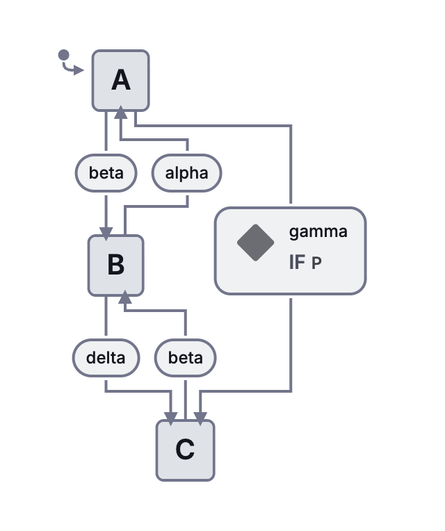
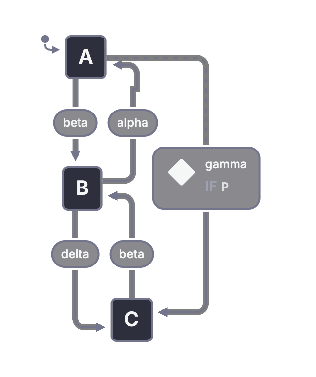
Flat diagrams become difficult when different parts of a system have independent states. A model with several independent choices needs a state for each permitted combination. Shared reactions also repeat. An emergency event that applies throughout a large operating mode may require many copies of the same arrow.
Harel summarizes the extension as:
statecharts = state-diagrams + depth + orthogonality + broadcast-communication.
David Harel, p. 233.
Here, depth means nested states. Orthogonality separates concurrent parts without listing every combination. Broadcast communication lets active parts coordinate through events. The following sections explain what each addition changes in the model.
The distinction matters when reading the rest of the paper. The number of possible system configurations does not disappear. The description becomes smaller because structure expresses relationships that a flat diagram would repeat.
2. State-levels: Clustering and refinement
Paper pages 234-242; Figures 2-18.
One parent can express a shared reaction
In Figure 1, both A and C have the same reaction to one event: move to B. Figure 2 places A and C inside a new state, D, and moves that shared transition onto D's boundary.
D is an exclusive choice between A and C. Being in A also means being in D. Being in C also means being in D. Being in D does not mean that A and C are both active.
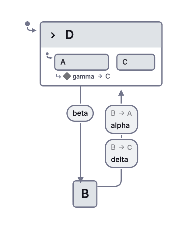
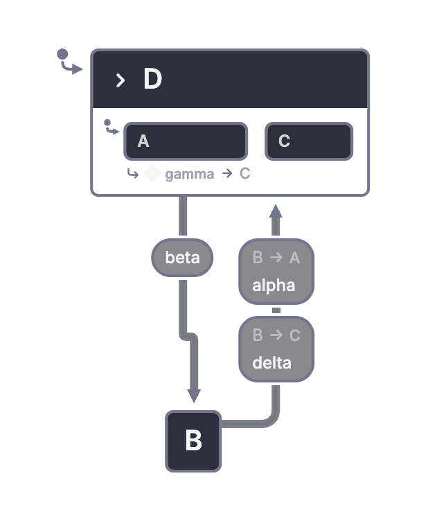
You can arrive at this structure in either direction. Clustering starts with detailed states and groups them. Refinement starts with a broad state and adds detail inside it. Figures 3 and 4 show the broad and refined views. Figure 5 isolates the inside of D.
Those views are useful only if the connections remain meaningful. An incoming arrow to D must say which child becomes active. It may target a specific descendant or use a default. Figure 6 compares ways to draw those defaults. In Stately, the initial-state arrow makes the default visible at each relevant level.
A zoomed-out picture must also preserve the difference between entering a parent normally and entering a particular child directly. Hiding the child's box does not erase that distinction.
The wristwatch becomes the running example
Figure 7 shows Harel's Citizen Quartz Multi-Alarm III watch and its four buttons, a, b, c, and d. The watch has time and date displays, two alarms, an hourly chime, a stopwatch, a light, a battery warning, and a beeper test.
The photograph introduces the physical device. Its native behavioral counterpart is the combined watch model below. A statechart describes how those controls behave; it does not replace a picture of the hardware.
Keep pressing a button separate from releasing it. The paper uses distinct event symbols for each. Our watch models use readable press and release event labels. That distinction becomes necessary when two buttons are held together.
Harel obtained the example by observing a finished watch. He also notes small differences between his description and the device. The example teaches a method of specification; it is not a manufacturer-certified hardware model.
Displays and alarm beeps share an outer structure
Figure 8 first separates normal displays from alarm beeping. Alarm 1, alarm 2, or both may beep, depending on the current time, alarm settings, and enabled status. A shared exit from the beeping parent handles a button press or the end of the beep duration.
Figure 9 refines displays. Repeated presses of a cycle through display modes. The time and date displays have their own connection through d, and remaining in the date display for two minutes returns to time.
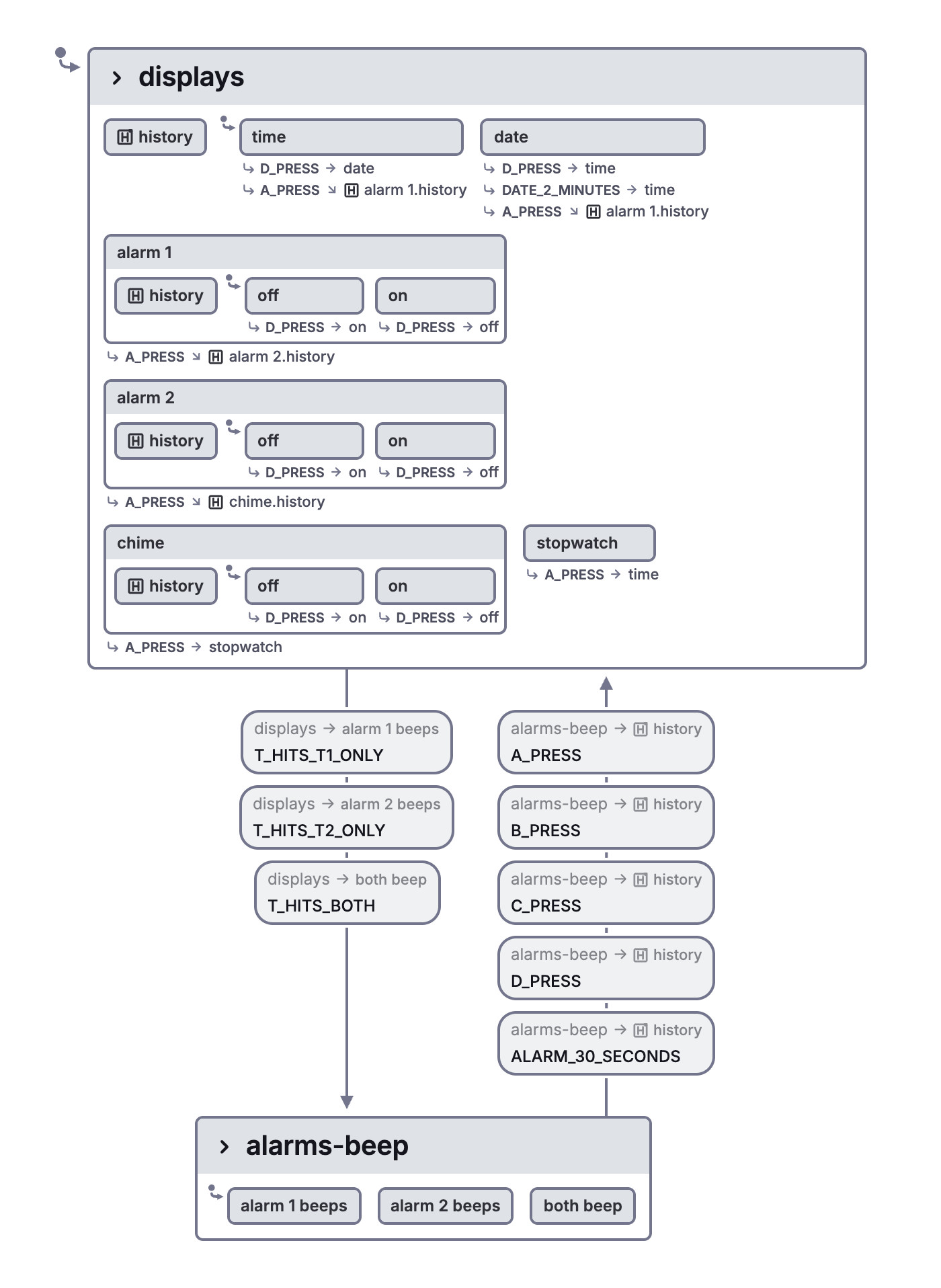
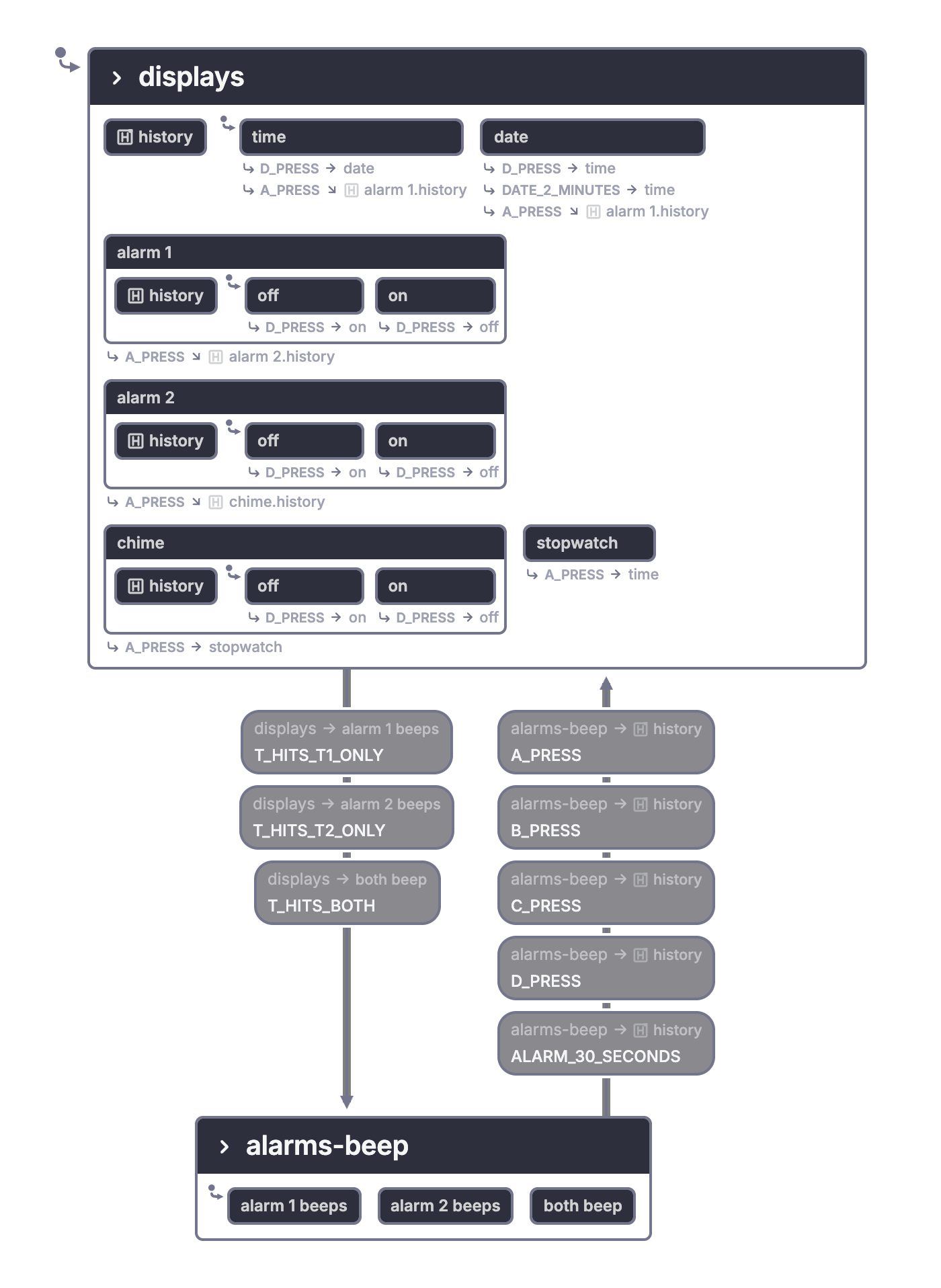
Initially, returning from an alarm beep could always enter the time display. The paper later changes that decision to restore the previous display through history. This is a concrete example of refinement changing an entry policy without abandoning the whole model.
The alarm conditions are initially written as abbreviations such as P1 and P2. Later, when alarm status has its own state, those conditions can refer to whether that state is enabled. A model can introduce an interface before all the internals behind that interface have been specified.
History chooses how much of a previous visit to restore
Figure 10 refines an alarm display into off and on. When the user returns to the alarm display, history restores whichever option was active. On the first visit, the default is off.
Figures 11 and 12 distinguish the amount of remembered detail. Suppose K contains G and F, and those states have children of their own. Shallow history restores the last direct child of K, then follows that child's normal default. Deep history restores the active descendants too.
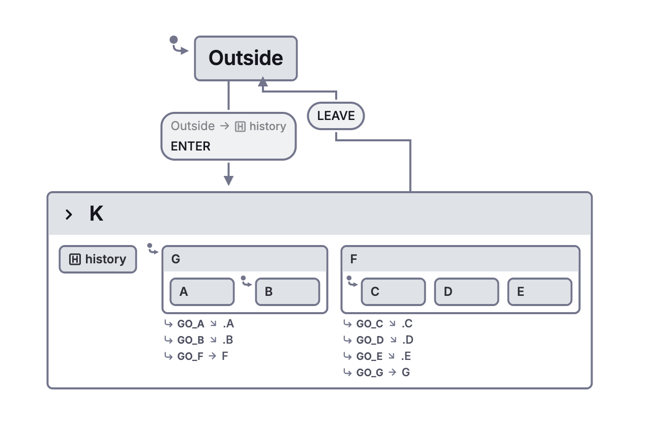
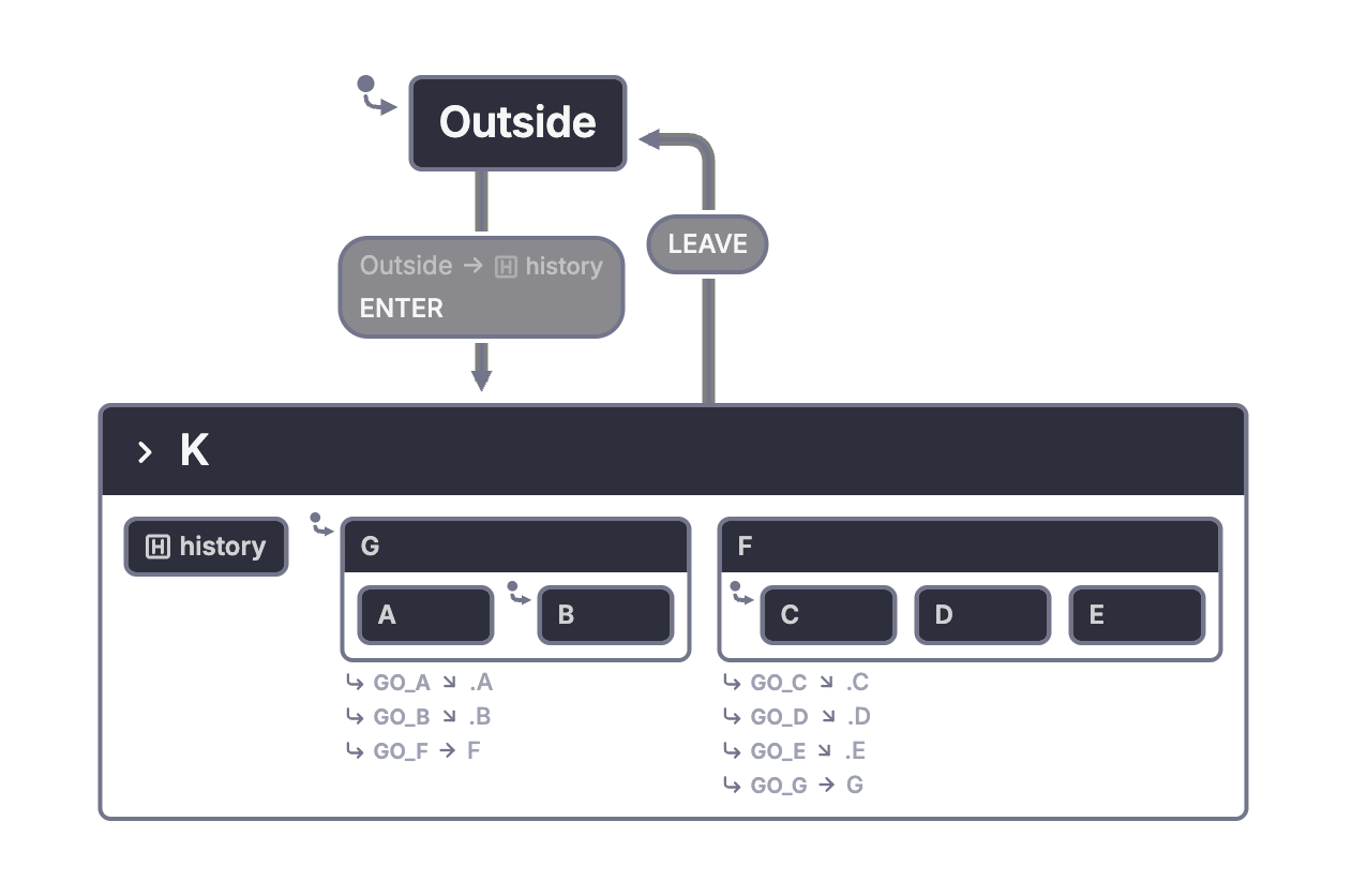
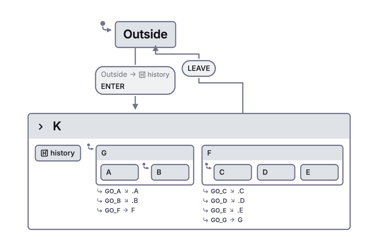
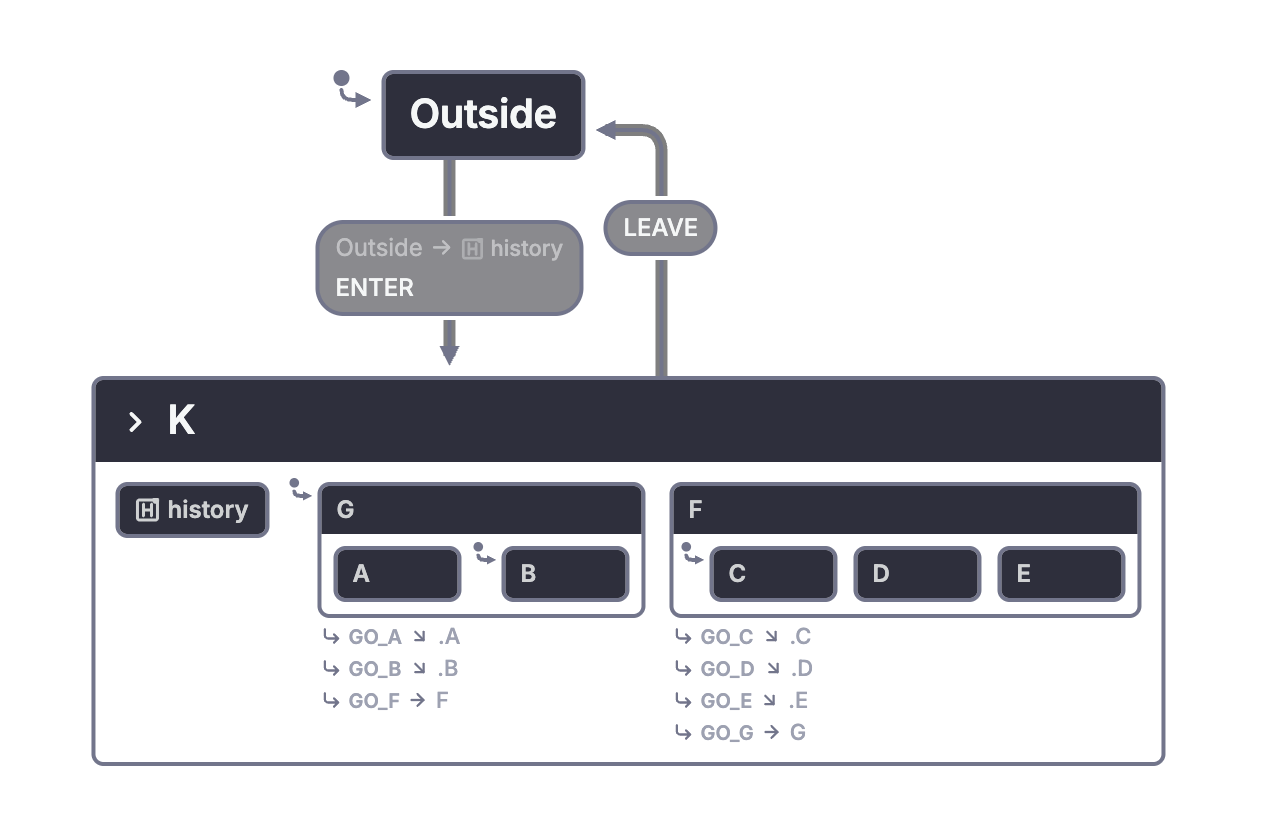
Figure 12 combines history at selected levels. Its purpose is to show that remembering one level and remembering every level are not the only possible policies.
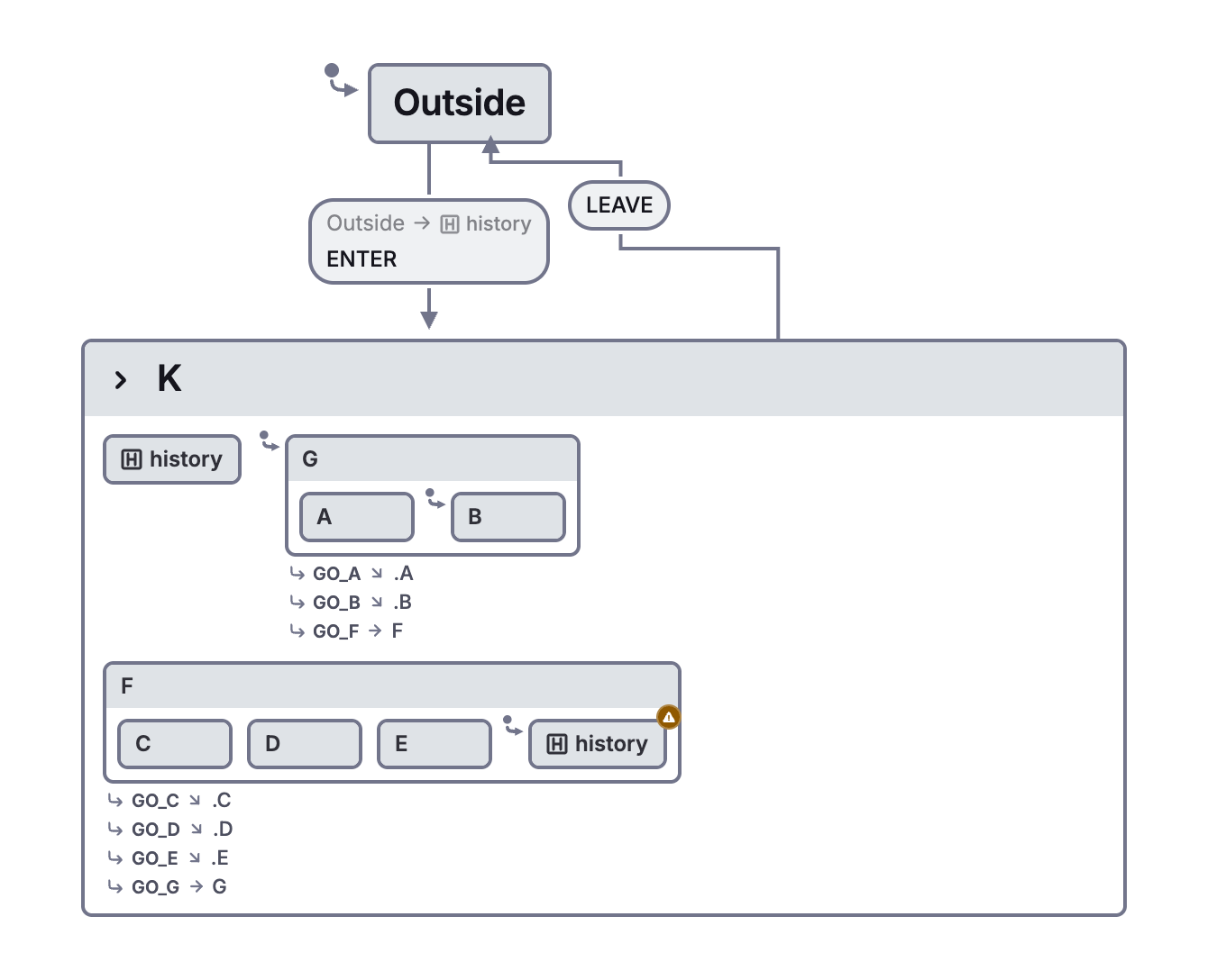
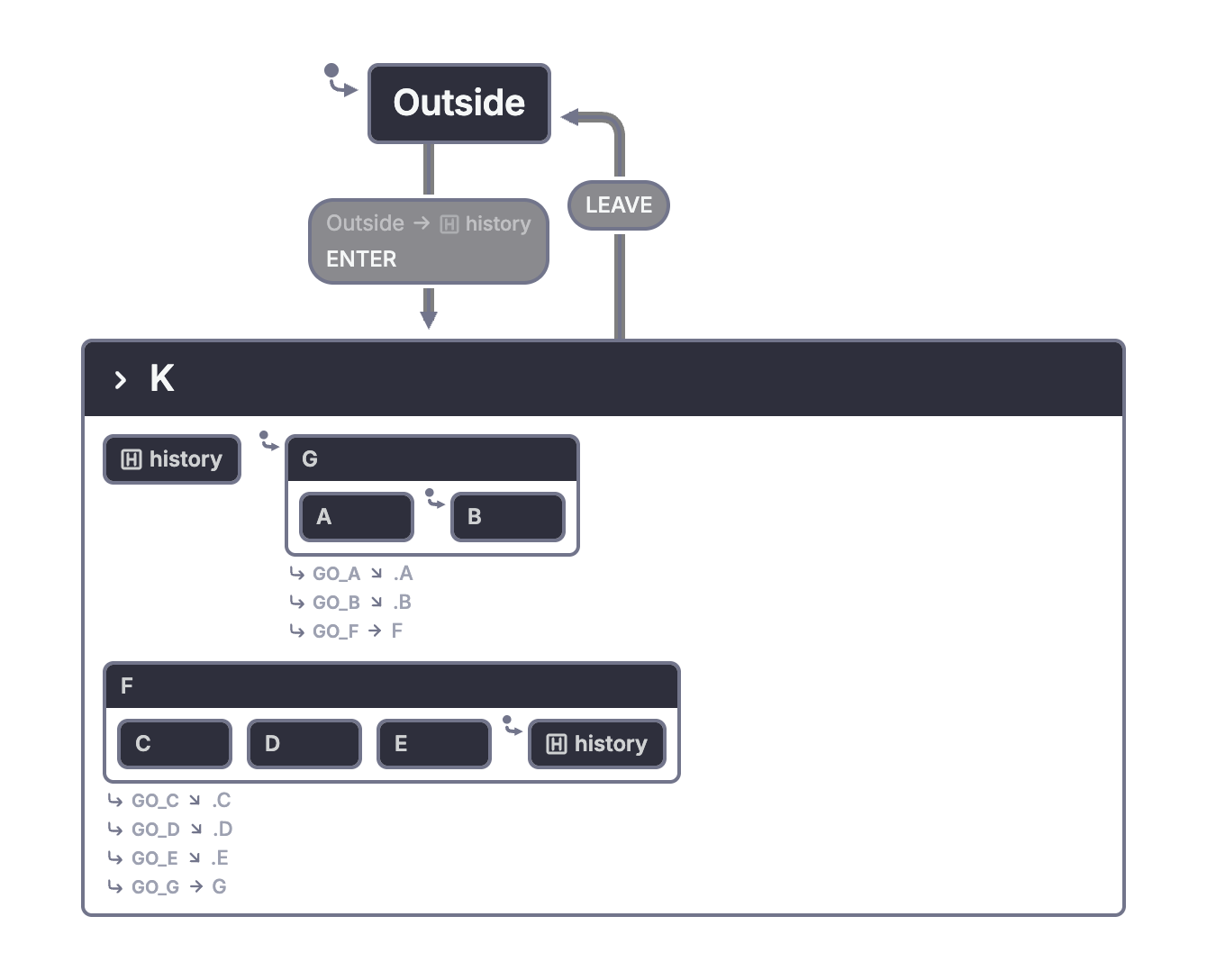
To reason about these diagrams, leave a parent while one of its non-default descendants is active. Then return through the history entry. Record the direct child and the leaf state separately. A test that only checks the direct child cannot distinguish shallow from deep history.
See history states for XState's rules and fallback behavior. Remembering a configuration within a running actor is separate from persistence across application restarts.
Updating adds detail inside display modes
Figure 13 adds update modes for the alarms and the time/date settings. The time/date path requires a continuous two-second press before updating starts. Pressing b leaves an update mode and returns to the relevant display.
Figures 14 and 15 refine the update modes into fields. The user can move between fields and increment the selected value. The arrow for incrementing may return through history to the same field. Remaining in the same visible field can still involve an action that changes data.
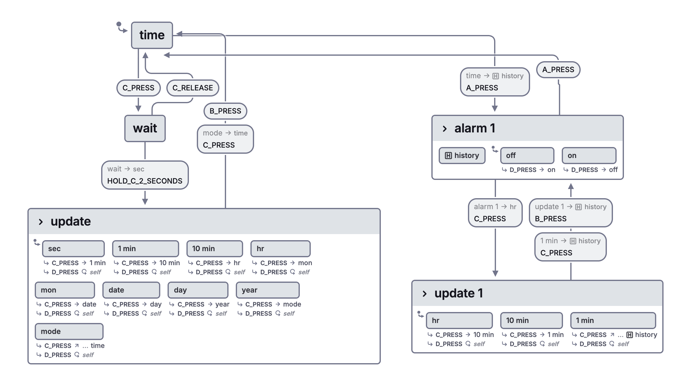
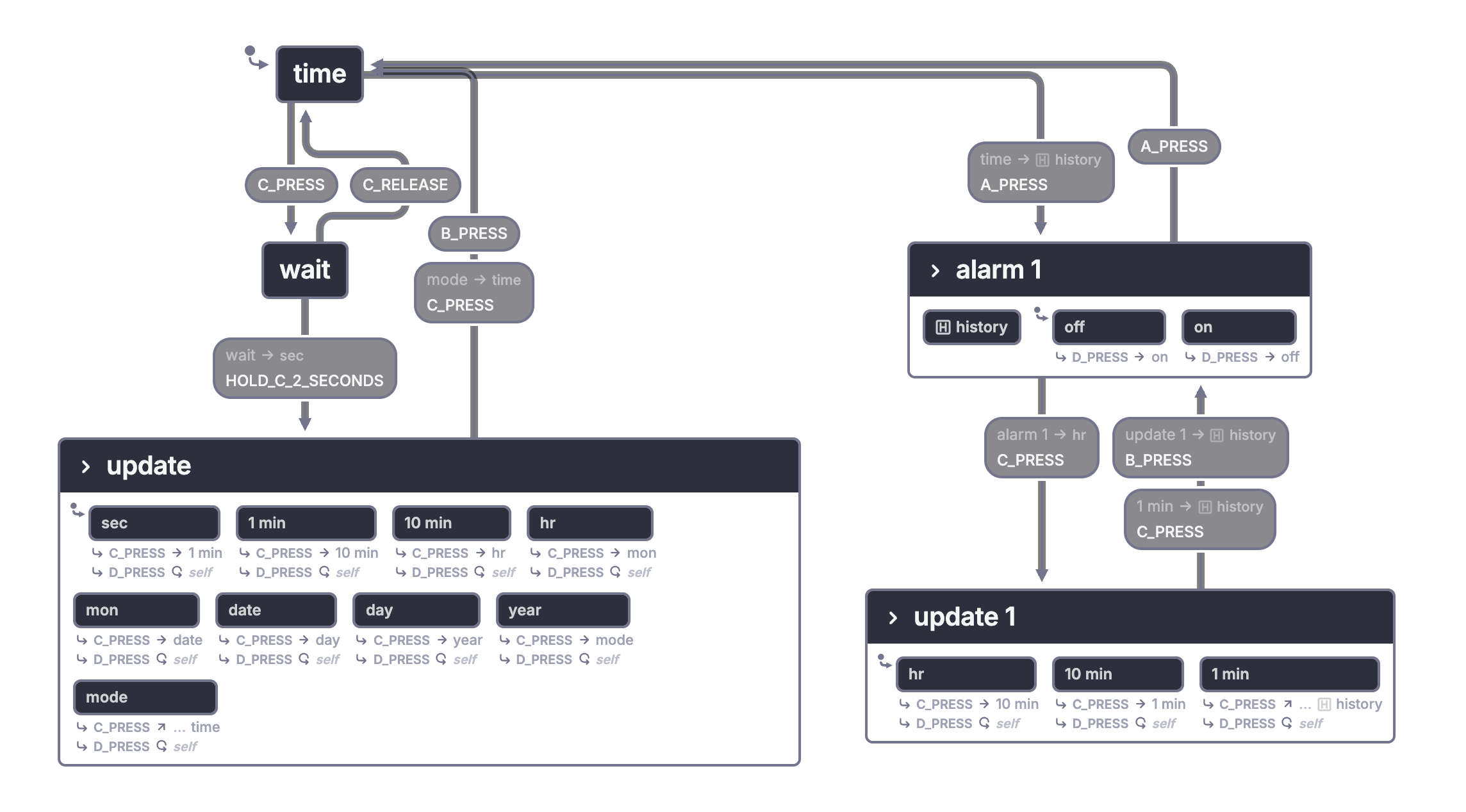
Figure 16 warns against an inaccurate abstraction. An exit available from only some children must not become an exit from the entire parent merely because the detail is hidden. The paper's stubbed arrow preserves that incomplete boundary information. In a native model, keeping the transition on its actual source child preserves the behavior. The adaptation uses a targetless action for incrementing the selected field. It retains the field without reproducing the original history self-reentry, so entry and exit effects are not implied.
Shorter drawings still need precise rules
Figure 17 shares pieces of arrows with common events, sources, or destinations. It is a drawing abbreviation. Expanding the abbreviation must produce the same transitions.
Figure 18 shows that nesting can create conflicts. A state and an ancestor may offer incompatible reactions, and competing default arrows may leave entry ambiguous. Harel treats these as problems a deterministic specification should avoid.
The flat and clustered adaptations above use explicit transitions and one initial choice at each compound state. They illustrate the resolved forms of Figures 17 and 18. They do not silently assign Harel's ambiguous picture a new meaning. XState specifies its own transition selection rules, including how child and parent handlers interact. Those rules do not retroactively resolve every ambiguity in the paper.
3. Orthogonality: Independence and concurrency
Paper pages 242-250 and the Figure 31 foldout; Figures 19-32.
One active configuration can contain several states
Section 2 uses an exclusive choice inside a parent. Section 3 adds a different relationship. When a parent has orthogonal components, being in the parent means being in every component at once. Each component can still have its own exclusive choices inside it.
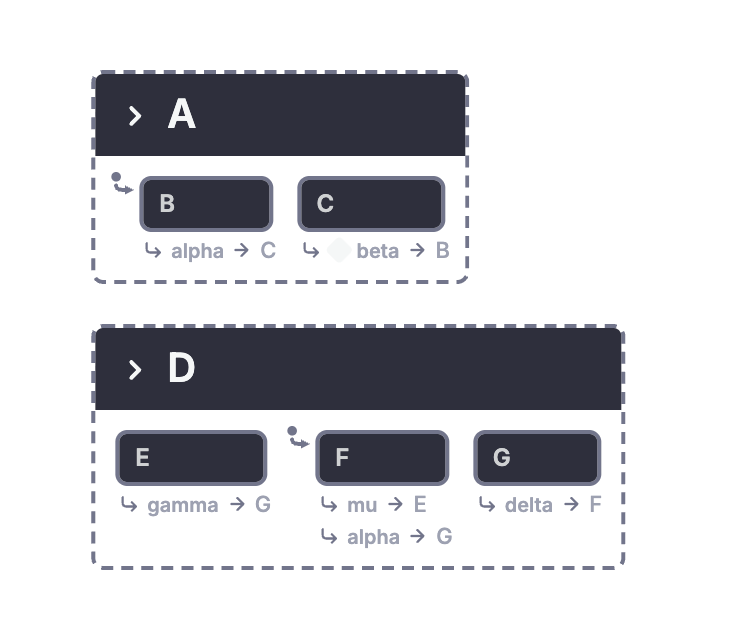
Figure 19 contains A, which chooses between B and C, and D, which chooses between E, F, and G. The default configuration is B together with F. One event can change both components, producing C together with G. Another event can change only one component.
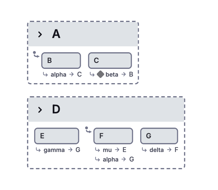
Here, concurrency means that several regions participate in the same system configuration. It does not require one operating-system thread for every region.
Figure 20 expands the same structure into six combined states. Compare the repeated transitions in that form with the compact parallel description.
Harel calls the growth an "exponential blow-up" (p. 243). Two regions with a thousand states each would require a million combined states in a flat description. Orthogonality lets us specify the regions separately; it does not remove the million possible combinations.
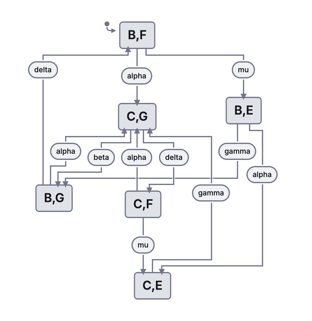
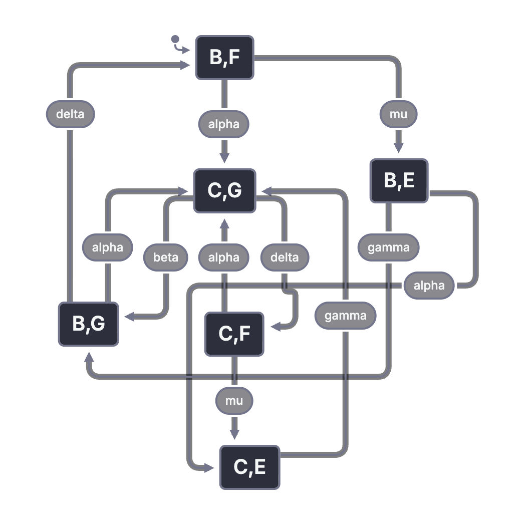
The components need not be completely independent. A transition in one region may be guarded by whether another region is in G. Shared events can coordinate both regions too. Orthogonality gives the model a way to separate concerns while retaining specified dependencies.
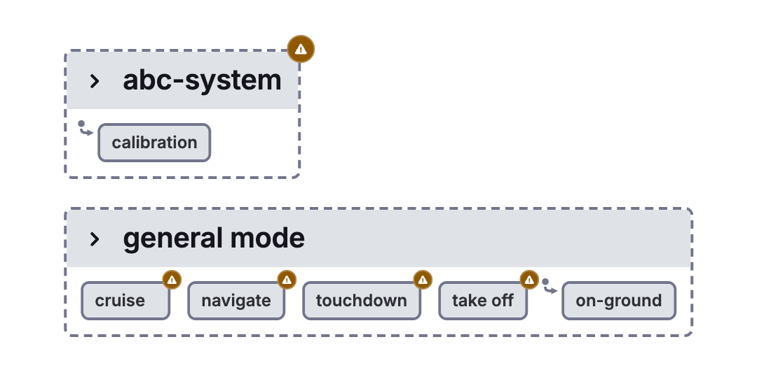
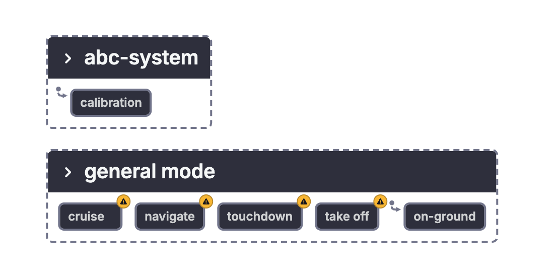
Figure 21 compares placements of the enclosing state's name. This changes the drawing, not the distinction between a compound state and a parallel state. Figure 22 applies the same decomposition to an avionics system, separating a general operating mode from subsystem modes. The original drawing supplies a structural sketch rather than a complete flight controller.
Entering and leaving a parallel state needs a policy
Figure 23 explores a parallel state's interface. A transition can select a particular child in both regions. It can select a child in one region and use the other region's default. It can combine a specific target with history in another region.
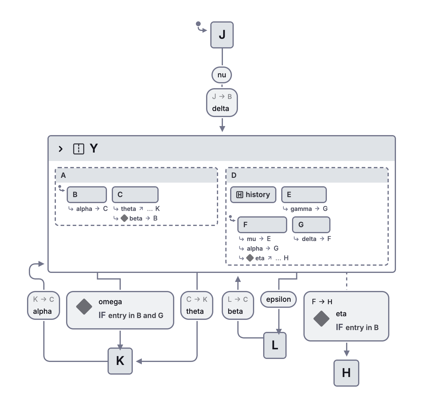
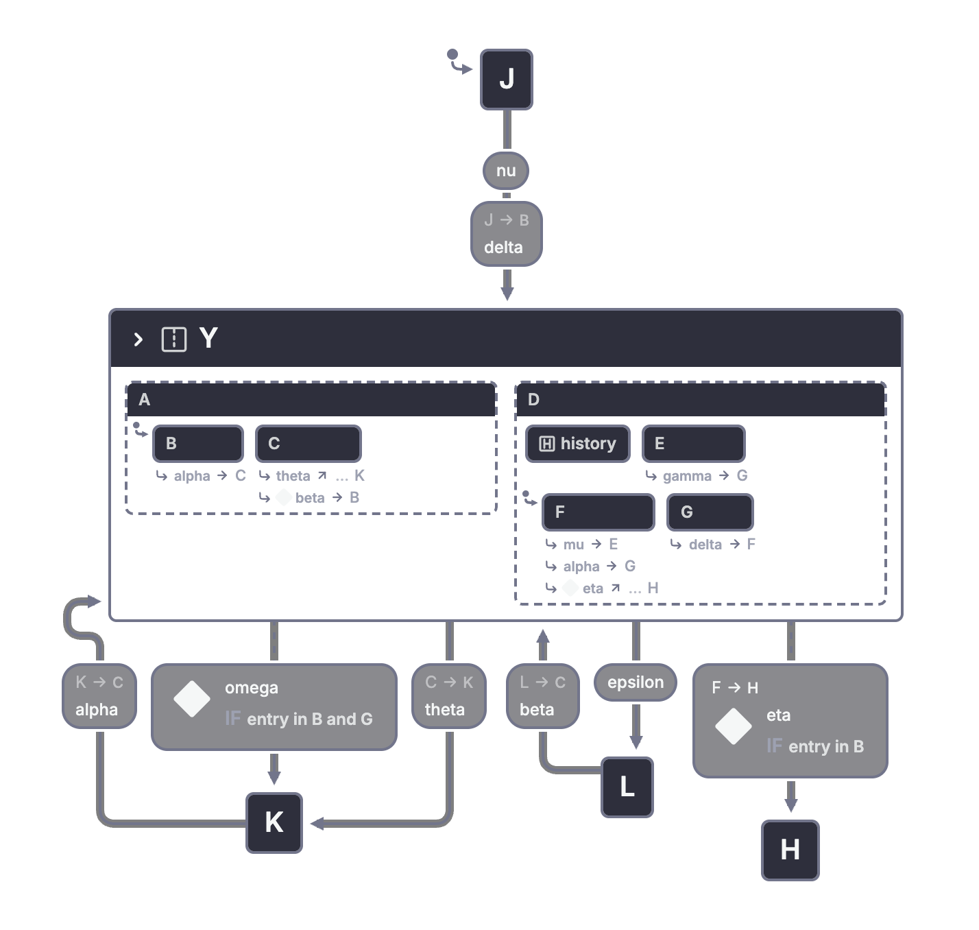
An exit may depend on a combination of states or on just one active child. Leaving the whole parallel parent also leaves its other active region. That differs from a local transition that changes one region while the others remain active.
Figure 24 hides the internal detail but keeps stubs for entries that cross a boundary. The lesson is the same as Figure 16: a compact view must retain enough interface information to remain honest.
The stopwatch separates running from displaying
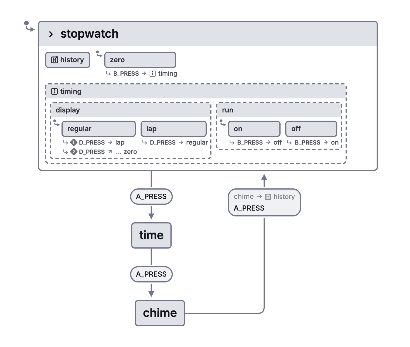
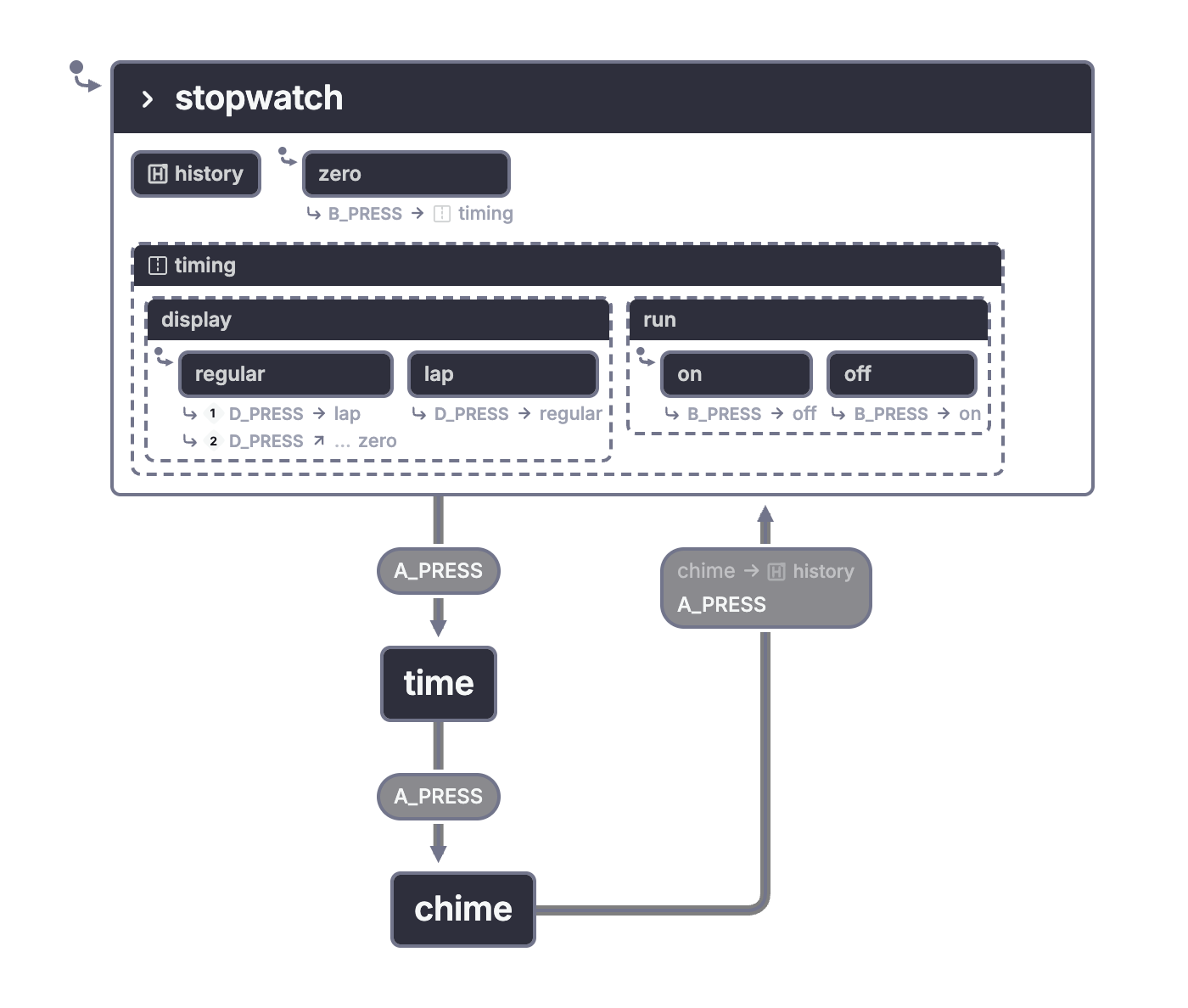
Figure 25 refines the stopwatch. The first visit starts at zero. Returning from the chime display uses explicit deep history to restore the last stopwatch configuration. Its display can be regular or lap while the counting mechanism is on or off. A frozen lap display does not imply that counting has stopped.
Open the stopwatch's independent display and run modes in Stately
This is a useful modeling question for interfaces too. Does a frozen screen mean that the underlying process is paused, or only that the displayed value is unchanged? Separate those choices when they can change independently.
The stopwatch also has a special zero state. Resetting to zero has conditions that differ from changing the display mode. The adaptation keeps that distinction rather than reducing the stopwatch to a single start/stop toggle.
The combined watch and a scenario
Figure 26 starts with battery insertion, battery removal, and battery death. Figures 27 and 28 refine the alive state into six concurrent components: main behavior, alarm 1 status, alarm 2 status, chime status, power, and light.
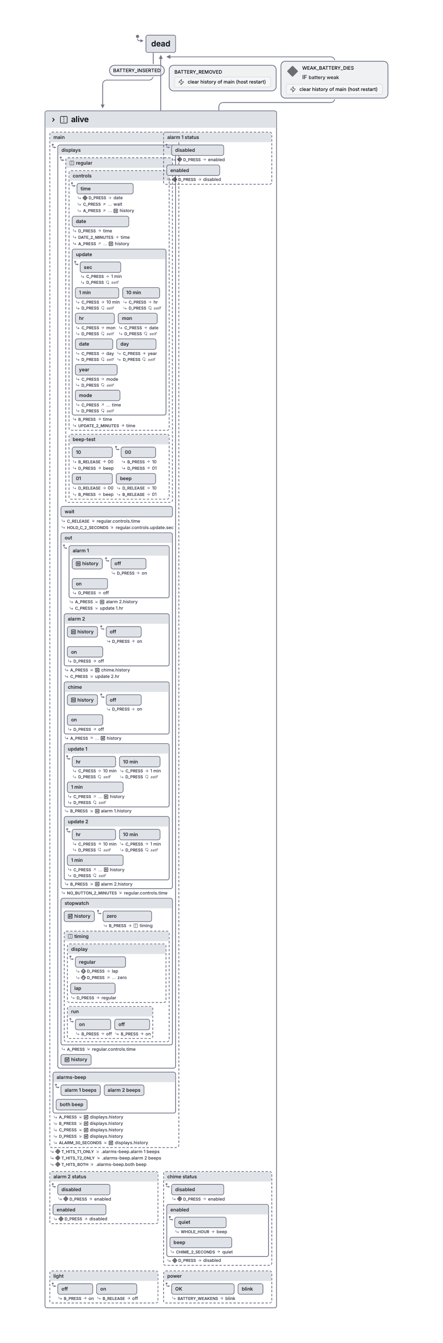
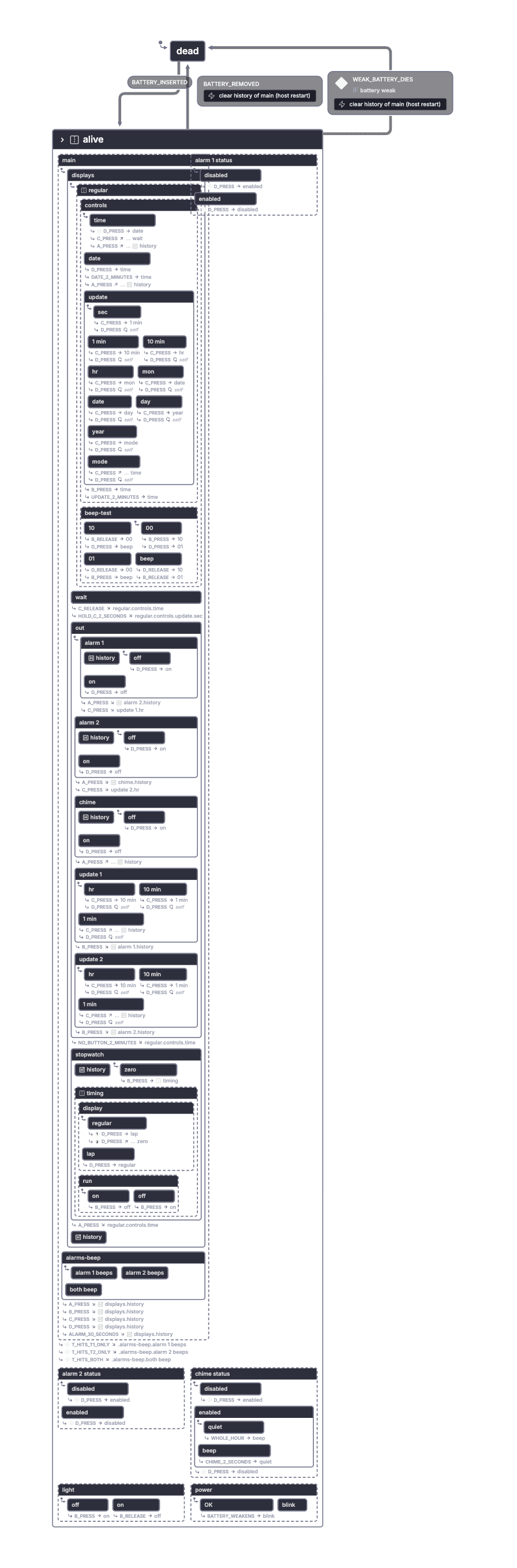
Placing the light at this level has a behavioral consequence. Pressing b can turn on the light while a different region responds to the same press. If the main region is updating a setting, that press can also leave update mode.
The enabled status of an alarm is likewise separate from whether its settings are currently displayed. Navigating away from an alarm display does not disable the alarm. Conditions controlling beeps can refer to the alarm-status region.
Figures 29 and 30 introduce the beeper test and show why its scope matters. Adding an orthogonal region to the time display makes the test available there. The actual watch also permits it in the date display and the general update sequence, but not in the two-second waiting period. Figure 31 groups the appropriate modes to express that boundary.
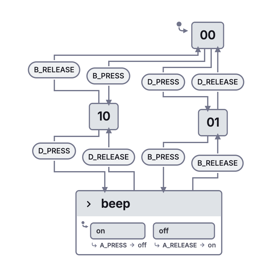
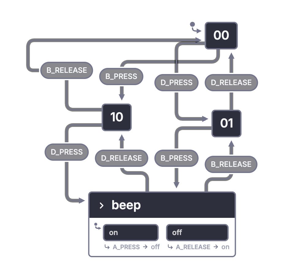
Harel checks the combined model with a scenario. Start while updating the month. Press d and hold it, then press b and hold it. The month increments. The main display returns to time. The beeper test sounds, and the light is on. A single sequence has consequences in several regions.
That scenario is more revealing than inspecting each region alone. It tests whether their scopes and shared events compose correctly.
The adaptation leaves physical timekeeping, display output, and numeric calendar arithmetic outside the state tree. Alarm and elapsed-time inputs are explicit model events. Those parts require an application implementation, as Section 5 explains.
The paper also clears remembered history when the battery is removed or dies. XState has no general clear-history action corresponding to the paper's notation. In the adaptation, beginning a fresh watch session is the reset boundary. Merely leaving a state and reentering its history must not be described as erasing memory.
Figure 32 adds an observed quirk omitted from the foldout. During a beeper test, holding a suspends the sound, and releasing a resumes it. The focused beeper-test view includes that extra refinement. The combined watch follows Figure 31 and leaves Figure 32 separate, as the paper does.
4. Additional statechart features
Paper pages 250-255; Figures 33-36.
The first examples establish the basic structure. Section 4 adds ways to express entries, timing, and large drawings more economically.
4.1. Condition and selection entrances
Paper pages 253-254; Figures 33 and 34.
An entry into a compound state may depend on a condition. Figure 33 introduces a circled C that abbreviates a set of conditional paths. It does not remove the need to define those conditions. If a compact drawing hides them, the full specification still needs them.
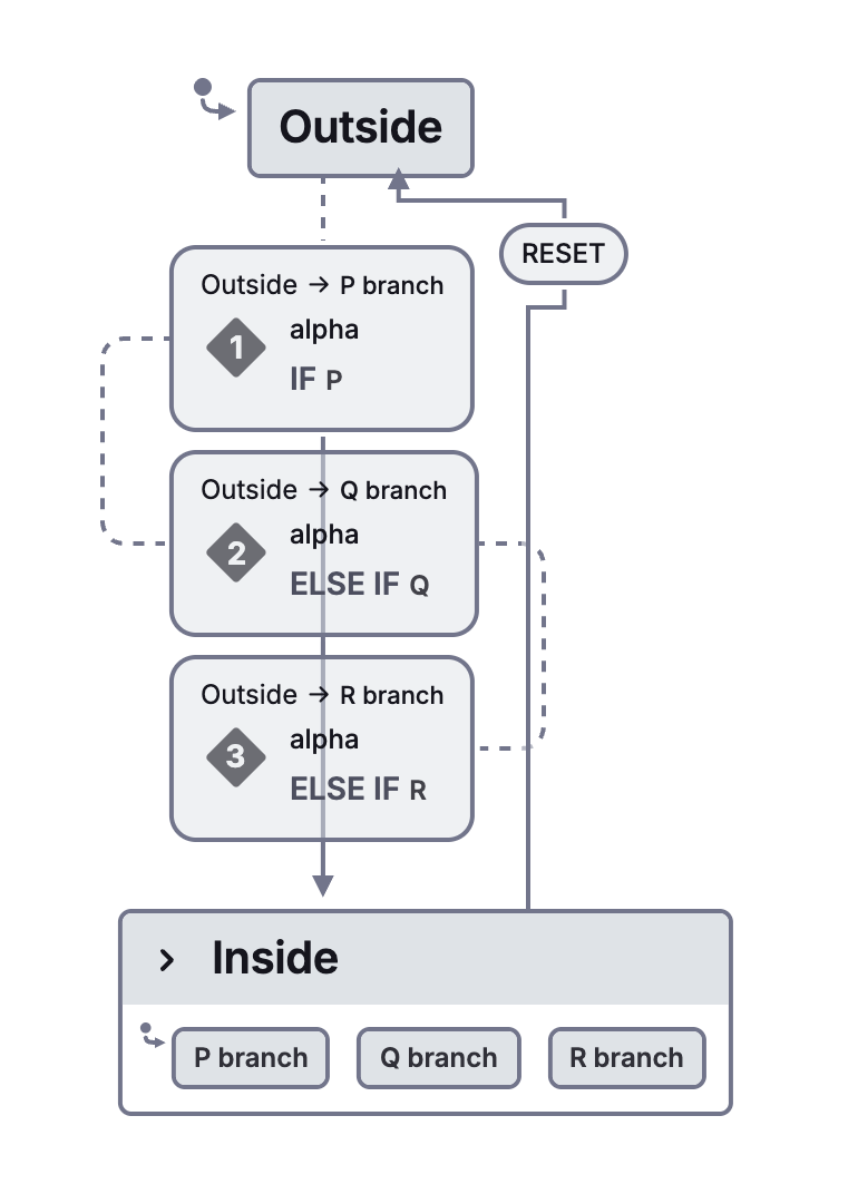
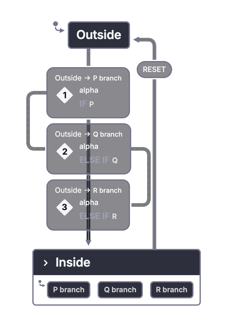
For a deterministic model, make the conditions mutually exclusive or define an intentional priority and fallback. An ordered list of XState guards is a particular policy. It should not be mistaken for an unspecified choice in the original figure.
A circled S abbreviates selection. Figure 34 uses a storage system with keys for type, name, quantity, and place. Selecting an option determines which update state to enter. The event-to-state association must be defined. In the adaptation, updating is a targetless action within the chosen field, rather than a history self-reentry.
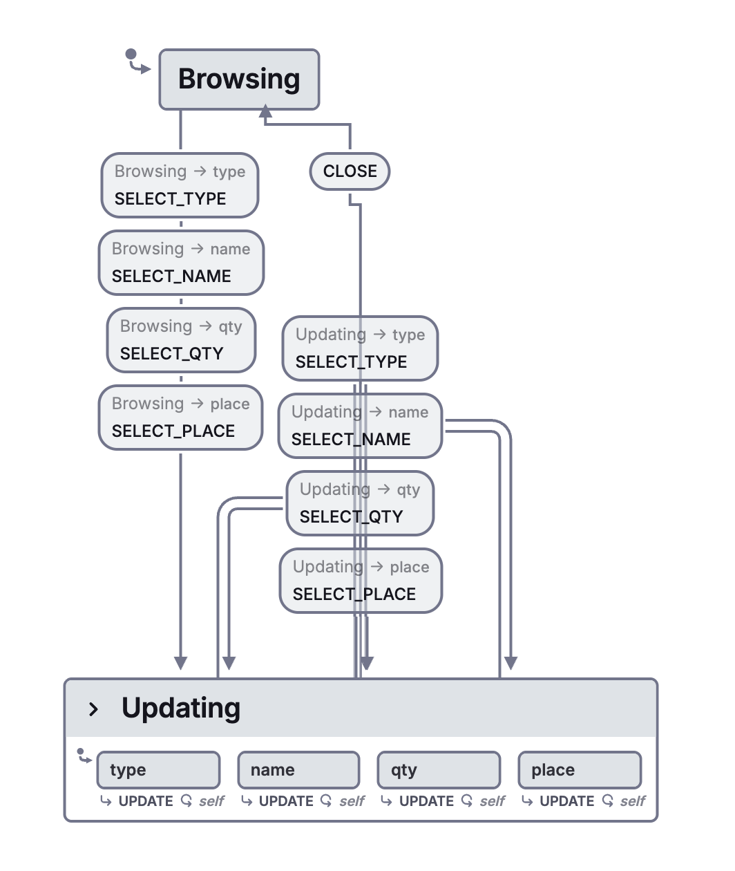
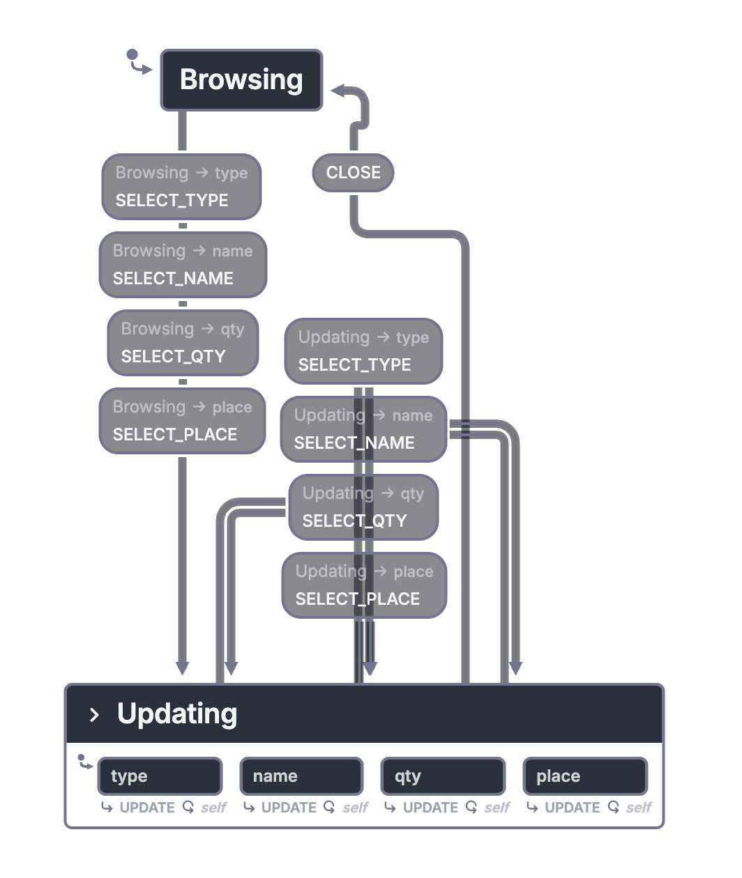
Conditional entry asks which condition holds. Selection entry asks which option the event selected. Both need concrete routing information. Neither connector is an unexplained jump to an arbitrary child.
4.2. Delays and timeouts
Paper pages 253-255; Figure 35.
The watch already uses elapsed time to leave a date display or stop an alarm. Harel describes a timeout relative to a specified event. A timeout relative to entering a state is one common case.
Figure 35 adds a state-duration annotation. An upper bound limits how long the system remains in the state. A lower bound prevents exit-triggering events from taking effect before enough time has elapsed.
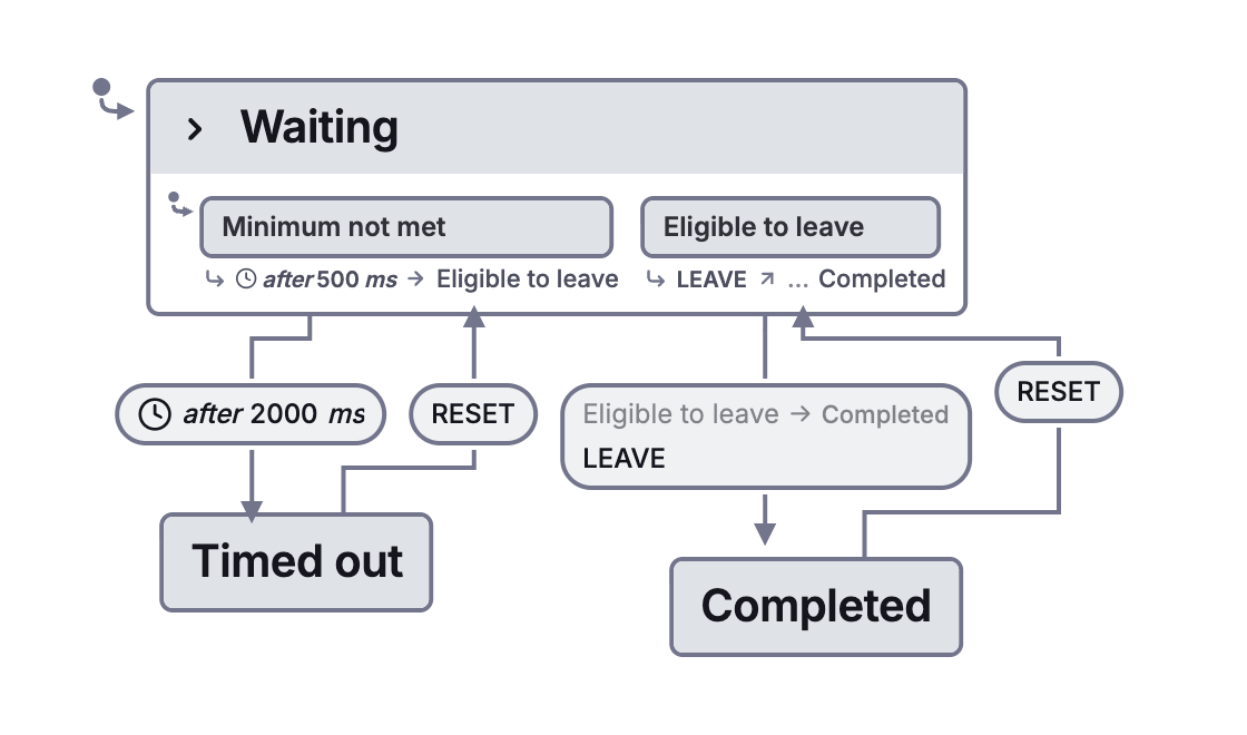
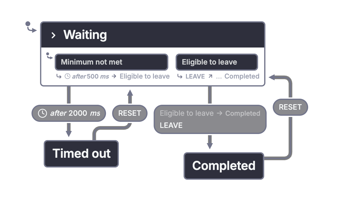
A useful concrete reading is a control that cannot finish during its initial protected interval, may finish after that interval, and must time out at its upper bound. The implementation must say which entry starts each timer, which exits cancel it, and whether reentry restarts it. This adaptation uses the figure's two-second upper bound and adds a half-second lower bound to illustrate the surrounding text. Its timers restart on entry.
In XState, delayed transitions describe state-relative delays. A timer that starts from an arbitrary event may need a different arrangement. JavaScript timers also do not turn a browser into a hard real-time controller.
4.3. Unclustering
Paper page 255; Figure 36.
Large statecharts can become unreadable even when their behavior is well structured. Figure 36 moves a detailed part outside its usual visual neighborhood while retaining its connection to the surrounding model.
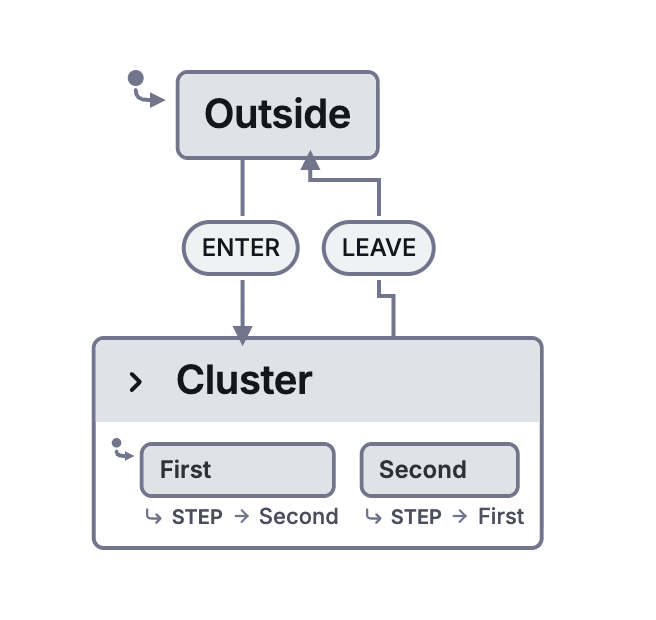
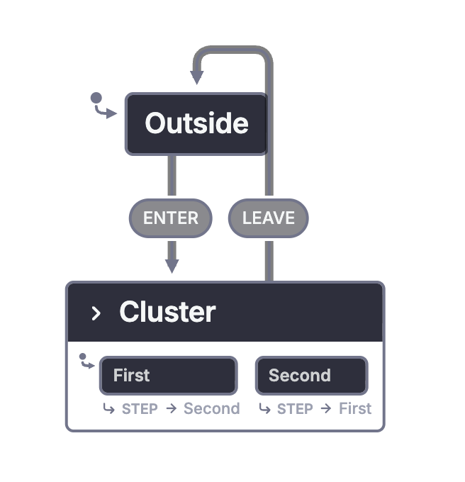
Unclustering is a presentation technique. It does not create a second independent instance of the state. The detached detail and the compact outer view describe the same part of the same system.
This is why zooming and focused views matter. A reviewer often needs to see one component clearly without expanding every other component at the same time.
5. Actions and activities
Paper pages 255-258; Figure 37.
Harel challenges what the watch diagrams have specified so far: have they established that the watch actually displays anything, beeps, or keeps time?
A state named beeping does not, by its name alone, make a speaker sound. Up to this point, most diagrams specify the control configuration. Section 5 connects that configuration to implemented effects through actions and activities.
An action is treated as an instantaneous occurrence in the model. Examples include assigning a value or emitting a signal. An activity takes time, such as sounding a beeper, displaying a value, or performing a computation.
Harel says actions take "ideally zero time" (p. 256). The qualification describes an abstraction used to reason about a reaction. It does not promise that a physical signal or a JavaScript function finishes in zero elapsed time. Work whose duration matters belongs in the activity part of the description.
The paper writes a transition label as α(P)/S: event α triggers it, condition P must hold, and action S occurs when the transition is taken. For activities, start(X) and stop(X) name the boundary actions, and active(X) asks whether the activity is running. These are the paper's concepts, not XState API calls.
Harel adds actions to transition labels and to state entry and exit. An activity associated with being in a state can be understood as starting on entry and stopping on exit. This gives the control model an explicit relationship with the rest of the system.
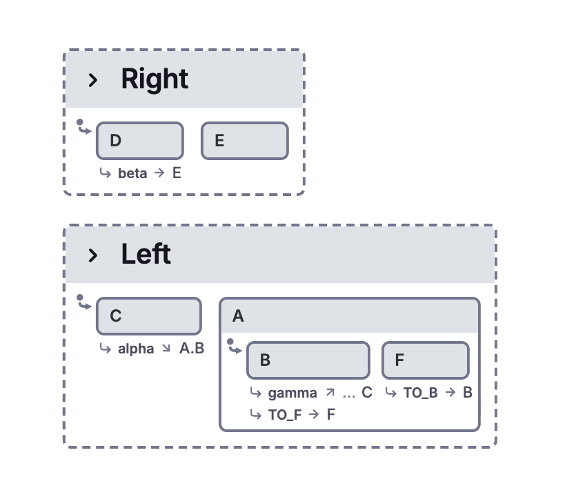
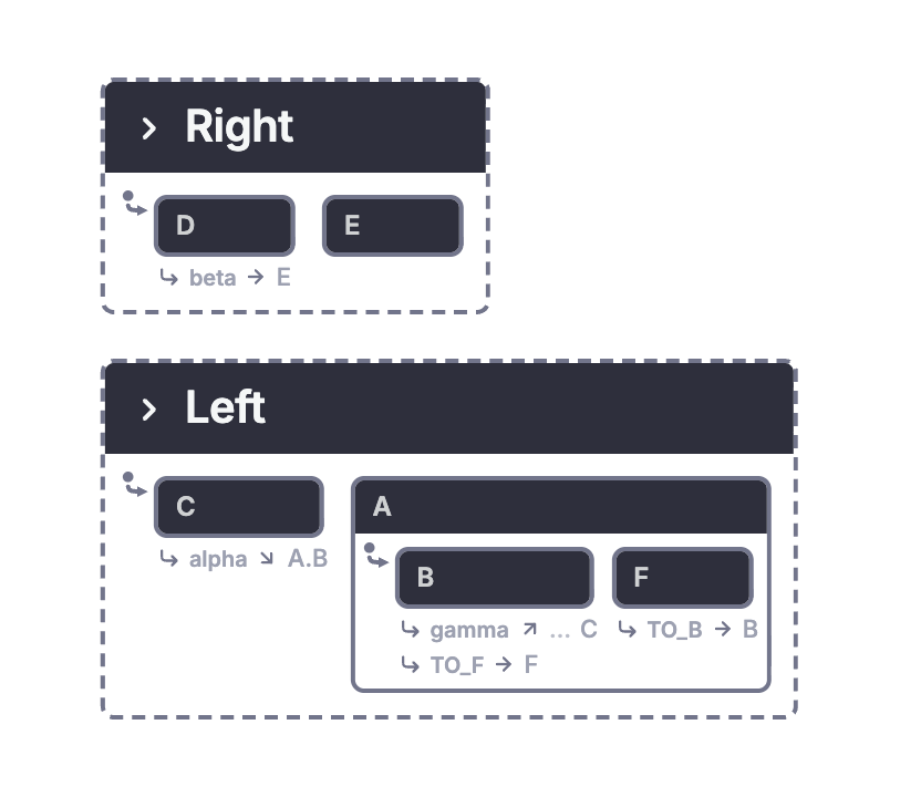
Open entry, exit, and communication between regions in Stately
In the paper's example, the initial configuration is C with D. An event moves the left region into A and its child B. A's entry action S and B's entry action V both apply. Moving within A from B to F does not enter A again, so A's entry action is not repeated.
Another transition leaves B and A. Their exit and transition actions apply, including generating beta. The other region responds to beta by moving from D to E and performing E's entry action U.
This is broadcast communication. One part produces an event, and other active parts can respond if they have an applicable transition. The paper's description treats these consequences within an idealized instantaneous step. XState's raised events have specific queueing and processing rules. The adaptation makes that internal event explicit; it does not claim identical scheduling across all statechart languages.
A long computation is not instantaneous just because an action starts it. In an application, invoked actors can represent work that continues while a state is active. Entry and exit can connect the model to hardware or other resources, but those effects still need implementations.
Harel also separates three questions: what physical components exist, what activities they perform, and what behavioral rules control them. Statecharts focus on the last question. He describes complementary module and activity diagrams rather than requiring one statechart to encode every structural and data-flow detail.
6. Possible extensions to the formalism
Paper pages 258-264; Figures 38-45.
This section changes status. Harel presents research proposals, often without a settled syntax or satisfactory formal semantics. Read the ideas as possible extensions to the basic formalism, not a checklist of features that every statechart tool must support.
6.1. Parameterized states
Paper pages 258-260; Figures 38-40.
Some state structures repeat with only a value or instance number changed. Figure 38 expands a minute digit into ten states, with increment transitions around the cycle. Figure 39 replaces that repeated structure with a parameterized description.
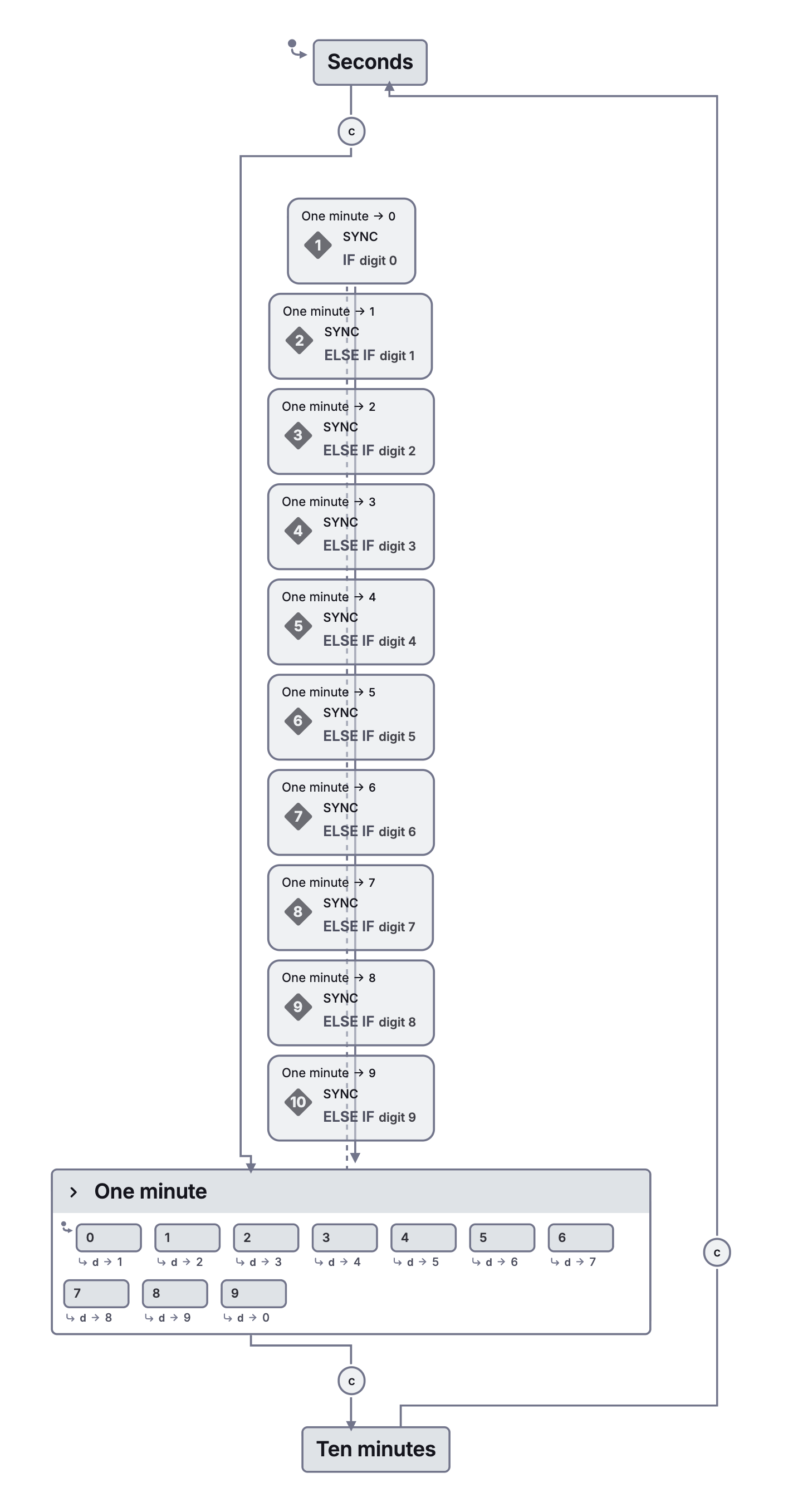
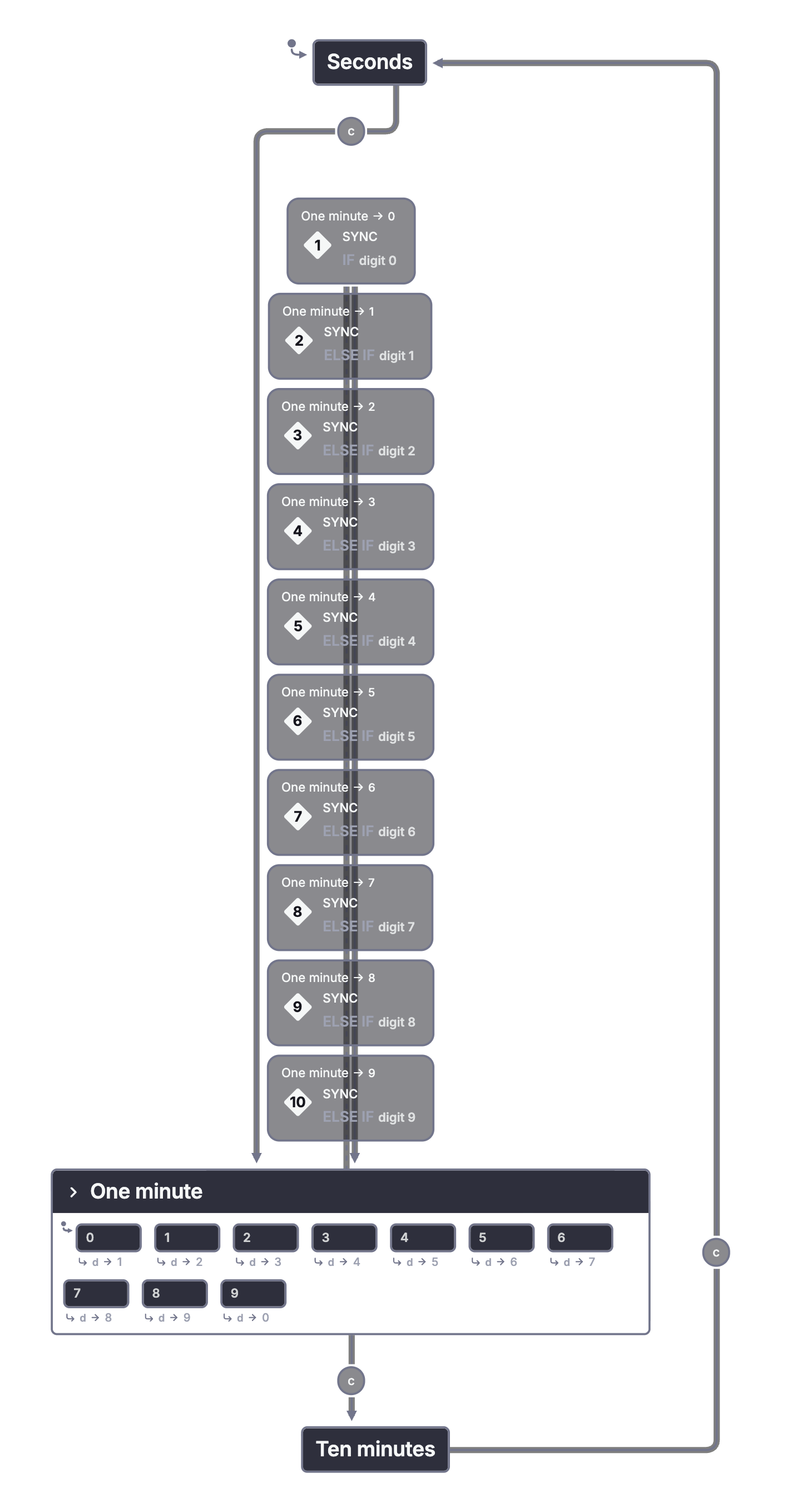
There are two distinct motivations. A parameterized exclusive choice can represent the value of a digit. A parameterized parallel structure can represent many similar components that are all present together.
Figure 40 uses a telephone network as the second case. Each telephone has a local state, while events coordinate interactions between telephones.
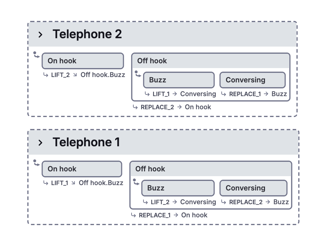
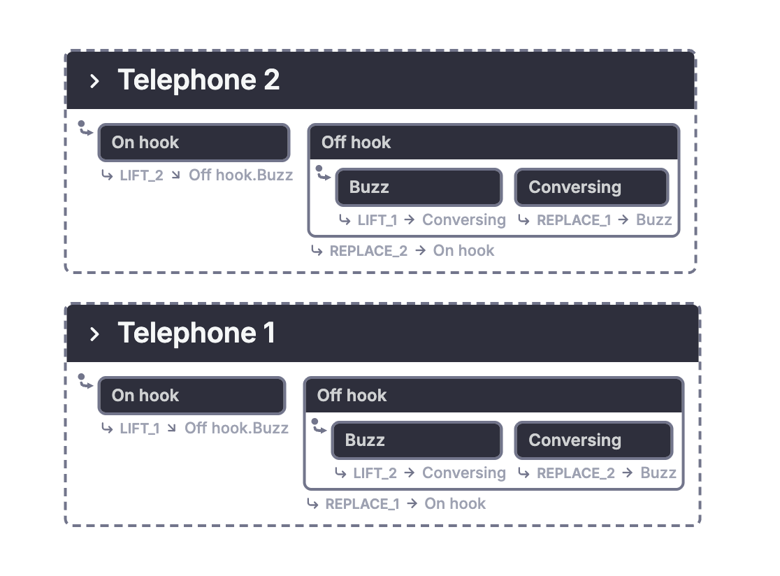
An XState application might put numeric values in context, create machine definitions with a factory, or create separate actors for repeated components. Those choices have different consequences. Ten digit states are a finite enumeration. A data variable is not automatically such an enumeration, and one thousand actors are not automatically one thousand parallel regions of a single actor.
The paper itself suggests that variables and richer data structures in a programming language may be the better representation for complicated parameterization.
6.2. Overlapping states
Paper pages 260-262; Figures 41-45.
The hierarchy so far is a tree. A state has one parent. Figure 41 asks whether a state could belong to two overlapping groups, perhaps because both groups share an exit condition.
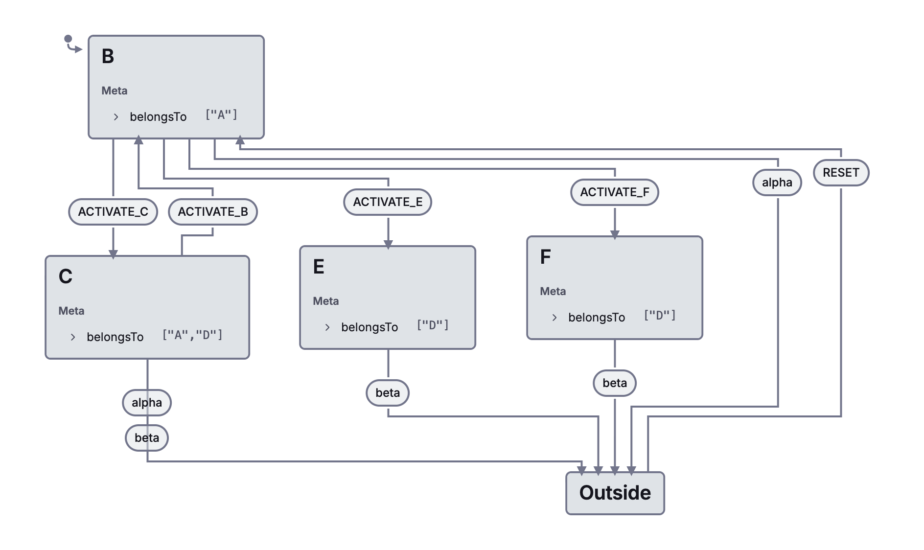
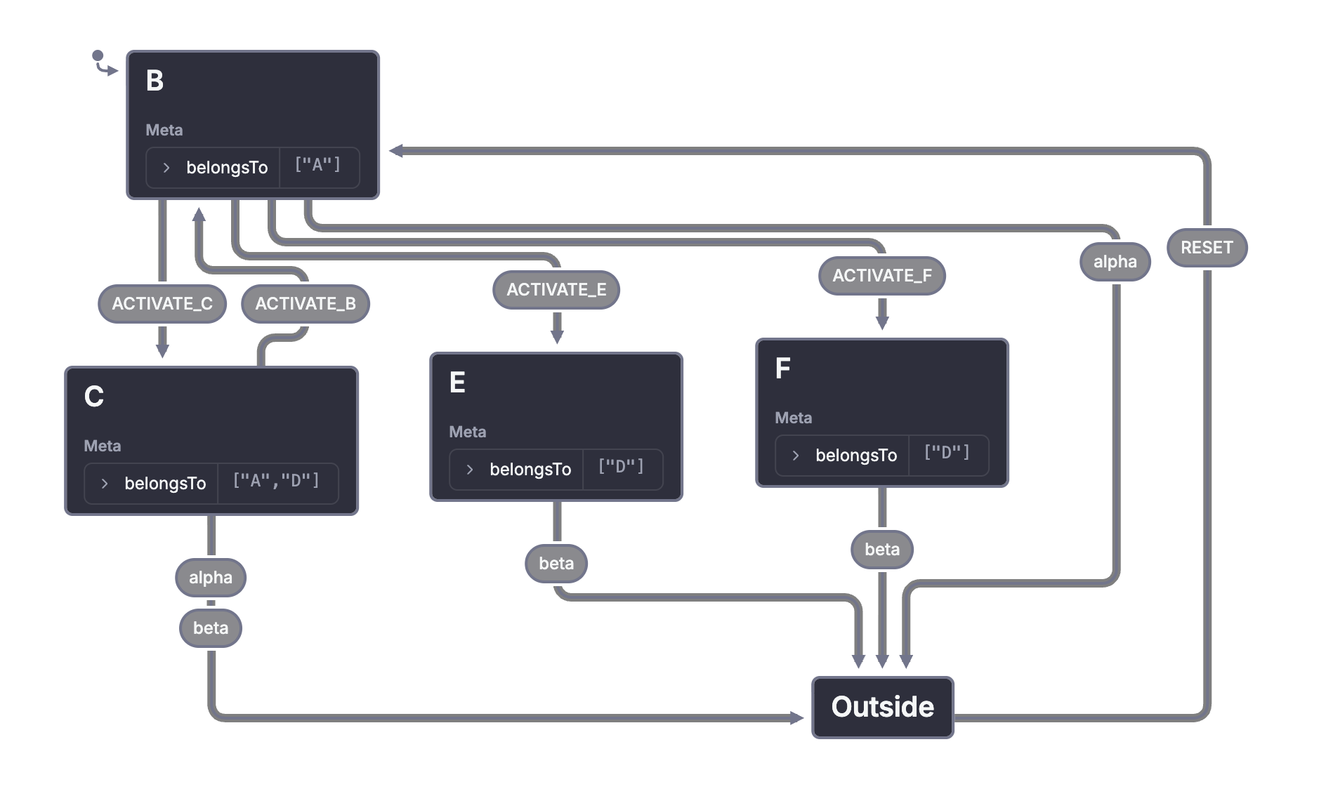
Figures 42 and 43 consider a related problem. A can exist by itself in one mode, but be active alongside B in another. One workaround repeats A. Another gives B an artificial state meaning that B is absent.
Harel proposes the overlapping representation in Figure 44 to avoid those compromises. Figure 45 then shows why entries need further notation. Entering a shared descendant must say whether it also enters the additional parallel component.
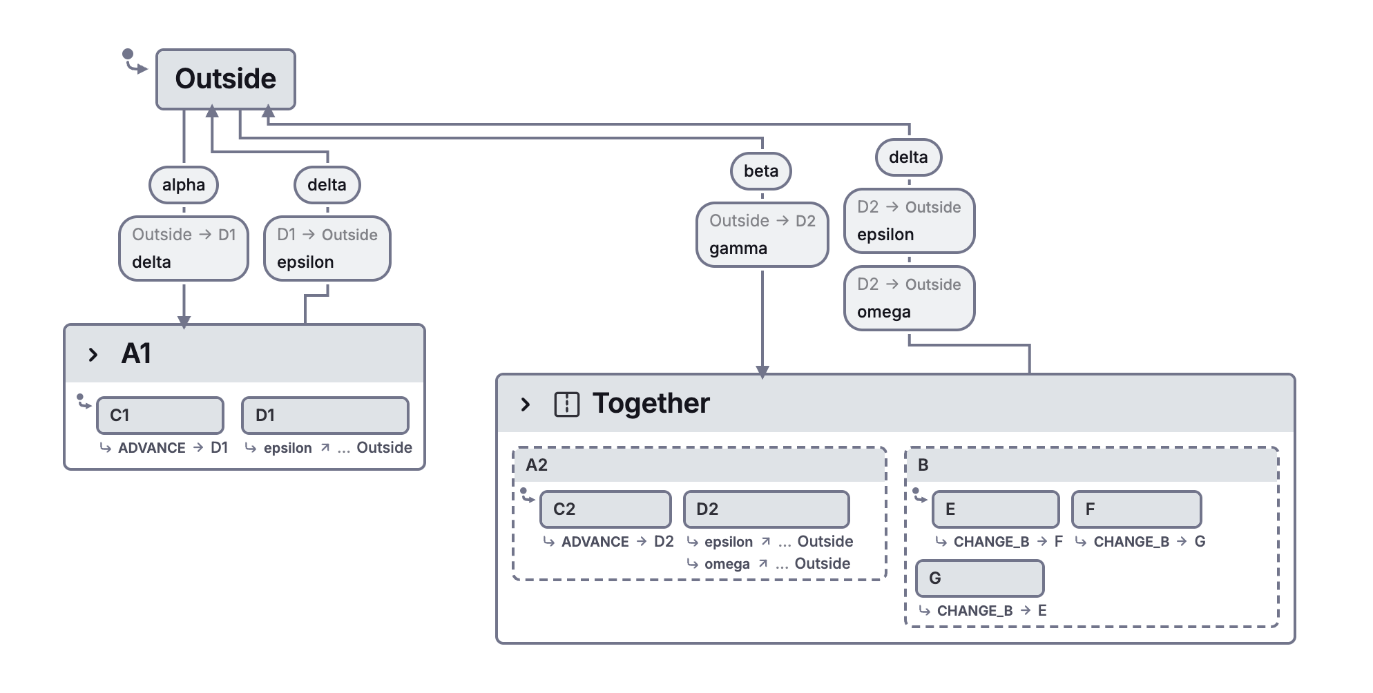
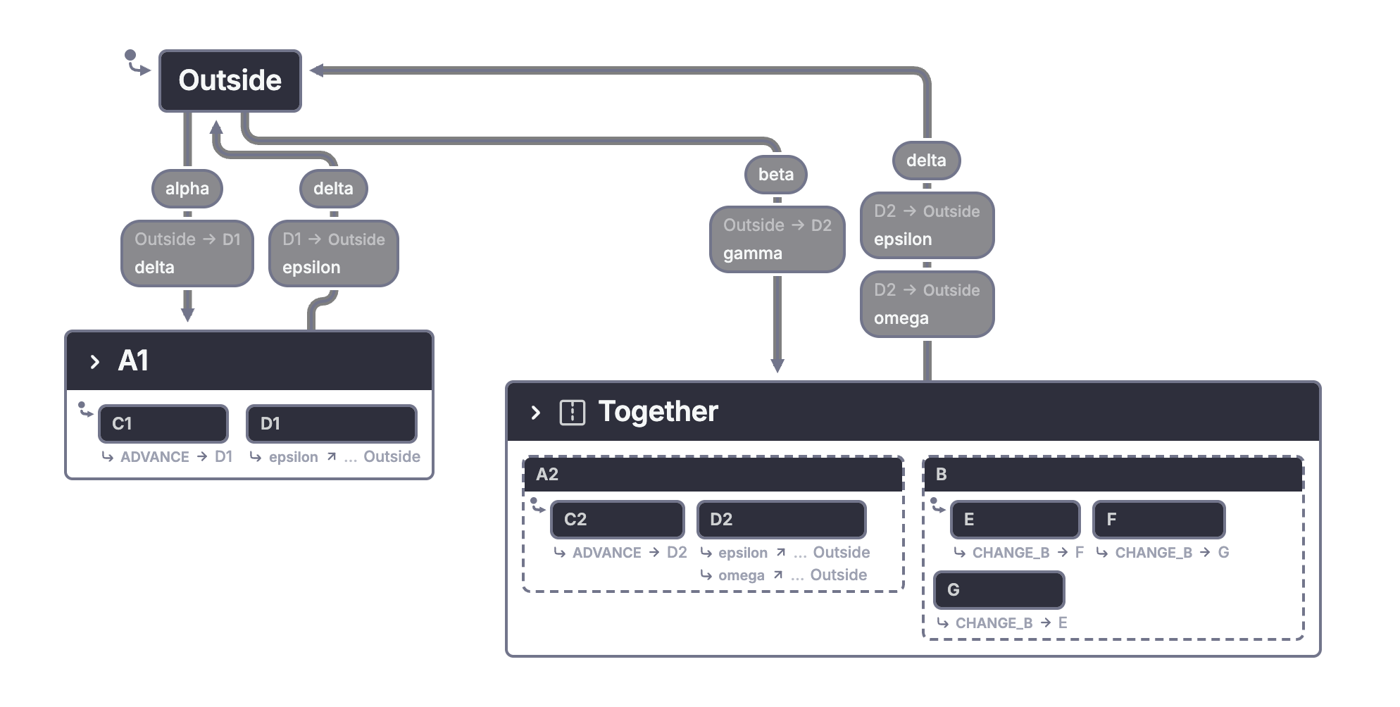
Figure 43's inactive-component workaround is also worth inspecting directly. B still exists as a region, but one of its states represents being inactive. That differs structurally from B not being present.
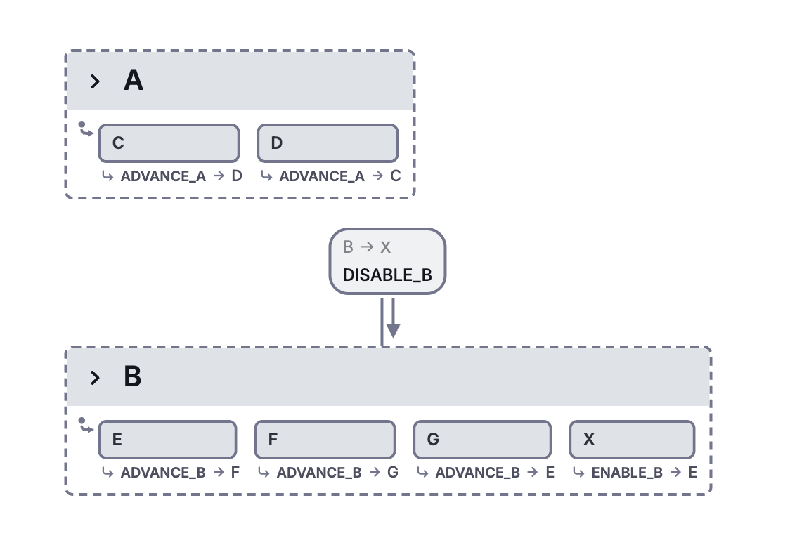
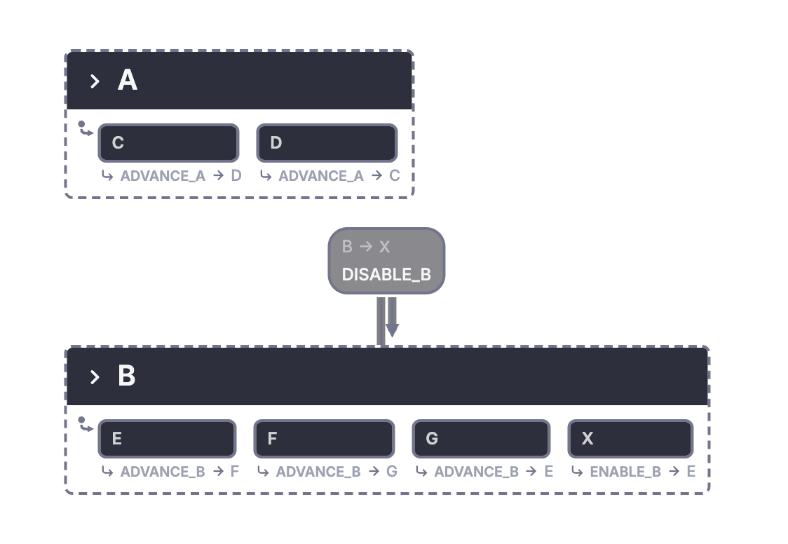
The native workaround is intentionally visible. Ordinary XState nesting cannot give one state two parents. Duplicating A can express a chosen finite behavior, but the copies have separate identity and history. Reusable definitions may reduce source duplication without making those runtime states identical.
The research proposal also introduces semantic questions, especially when overlap interacts with orthogonality. The paper does not present overlap as a finished, universally supported feature.
6.3. Incorporating temporal logic
Paper page 263; no new figure.
A statechart describes how behavior evolves. A temporal assertion can state a property that should hold across many evolutions. For example, a requested operation may eventually need a response, or an invalid combination may have to remain unreachable.
Harel proposes several relationships between temporal logic and statecharts. We might verify that a statechart satisfies temporal requirements. We might synthesize a statechart from requirements or scenarios. We might also use statements about the past as conditions inside a model.
His watch example asks whether the chime was previously on, with no intervening visit to the chime display or dead state. Ordinary history captures a useful subset of such questions, but does not express every condition about an arbitrary past sequence.
A practical application can record facts needed for a particular policy in context or explicit states. That is an implementation of that policy, not a general temporal-logic engine. Likewise, checking a few event sequences does not prove an eventuality for every possible execution.
This subsection has no figure to convert. The history examples earlier supply the concrete contrast between remembering a recent configuration and stating a more general property of the past.
6.4. Recursive and probabilistic statecharts
Paper pages 263-264; no new figure.
Recursion would let a transition call another statechart and continue when that call terminates. Harel connects this idea to augmented transition networks and notes the need for terminal-state notation.
An invoked child actor can be useful in a modern application, but invocation alone does not establish the call/return and recursive semantics proposed here. A self-transition is not recursion either. It reenters behavior without necessarily creating a new nested call.
The probabilistic proposal starts from a nondeterministic choice and adds probabilities to its alternatives. The intended distinction is between several allowed next outcomes and a distribution saying how likely each outcome is.
A deterministic guard list does not express that distribution. An application can sample randomness and pass a result into a machine, but then the source of randomness, probabilities, and analysis assumptions must be defined separately. There is no extra illustration in this subsection, and the paper does not supply a complete implementation recipe for either extension.
7. Semantics of statecharts
Paper pages 264-267; Figures 46-49.
A diagram becomes executable only when rules determine its meaning. Nesting and parallel regions explain much of the structure, but generated events, state conditions, and competing transitions make execution more subtle.
A shared picture does not guarantee a shared result
Figure 46 begins in A with B. One alpha event leads to C with D. On the next alpha, the competing transitions permit E with H or G with F. The paper explicitly says that taking both destinations as E with F is not the result.
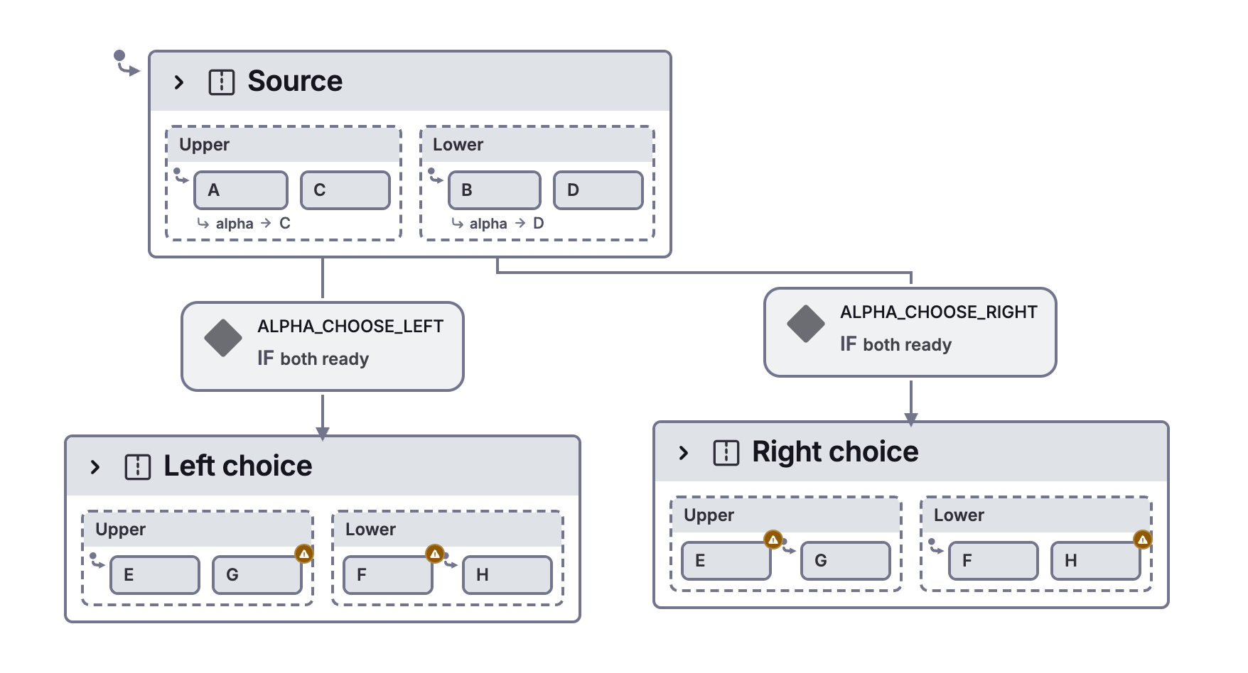
That example is a warning against reading each arrow independently and combining all the targets. Transitions can conflict because of the configurations they leave, even when parts of their drawings look separate.
Generated events can create cycles
In Figure 47, one region emits an event that causes another region to emit the next event. Following the chain returns to the first event.
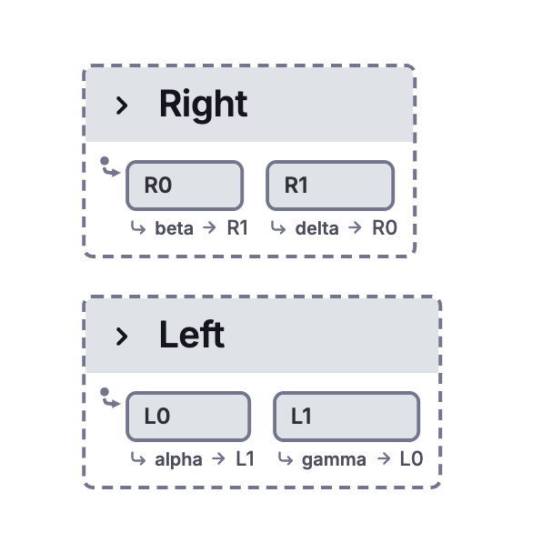
Without a rule that rejects, bounds, or otherwise defines that behavior, a reaction may never reach a stable result. The drawing alone does not guarantee that one external input finishes processing.
State observations need a defined time of observation
Figure 48 starts with A, C, and E active. Alpha changes A to B. Another region responds to entering B. A third responds to alpha only if A is active.
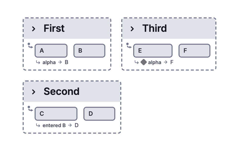
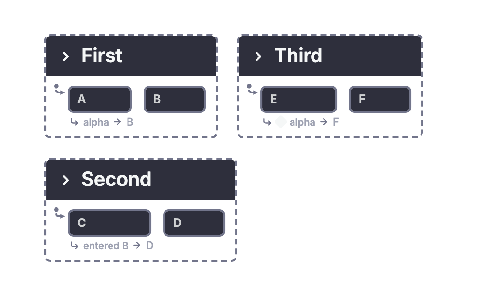
Does the guard observe A before or after the first transition? Is an entered-state event visible during the same step? Harel lists four candidate results and says that a formal semantics must settle the question. His intuition is not a substitute for the rules.
The JSON labels the action that raises entered B. With the companion's supplied XState guard and action implementations, alpha selects transitions against the current configuration, then entering B raises entered B for an internal microstep. The final configuration is B, D, and F. That is a concrete interpretation to inspect and test. It is not evidence that the original paper requires the same interpretation.
Simultaneity and absence are different from event order
Figure 49 sends A to B on alpha together with beta, or to C on alpha without beta. A third arrow goes to D on gamma together with the event of leaving A. Can gamma cause that departure when leaving A is itself a prerequisite? That causal question makes the example harder than ordinary ordered input.
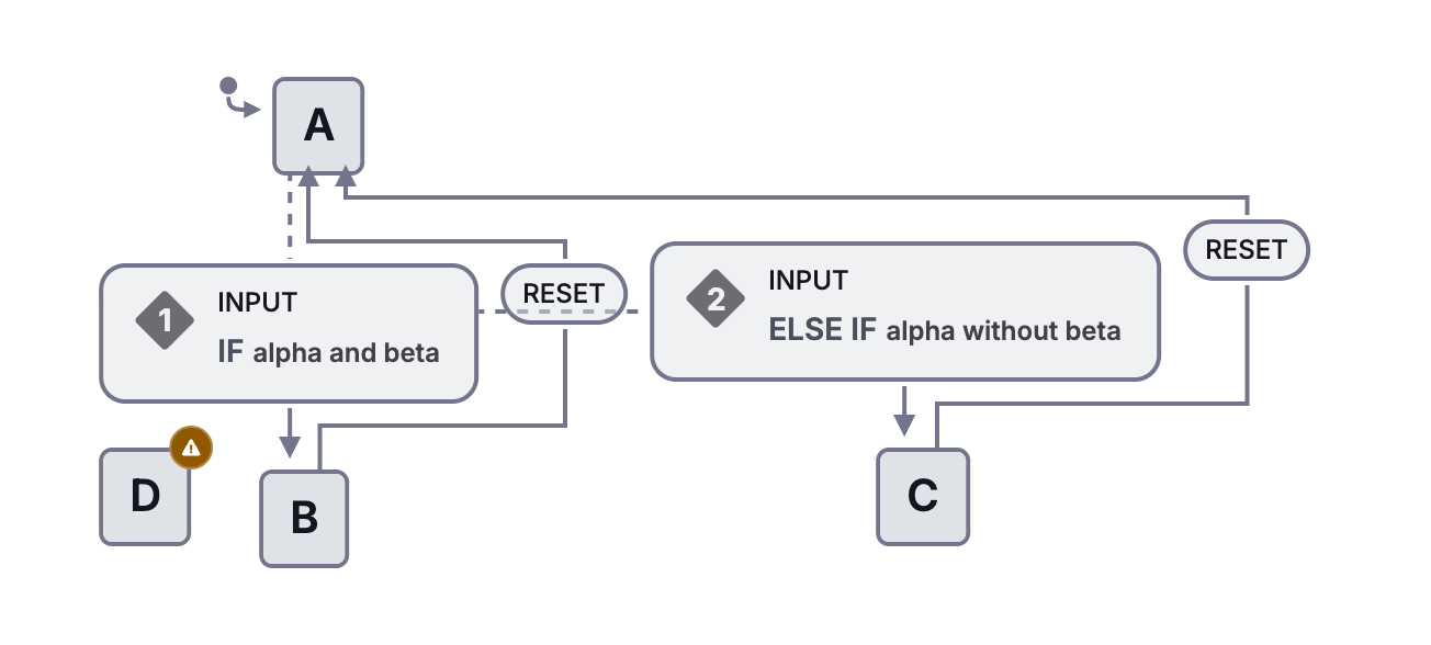
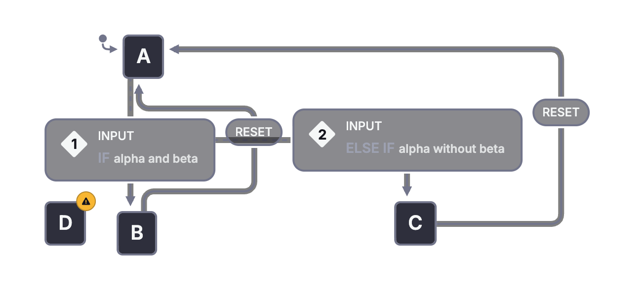
The adaptation accepts an INPUT packet with explicit observations. Alpha with beta chooses B; alpha without beta chooses C. Gamma alone stays in A, and D remains unreachable. That declared policy does not solve the paper's causal question.
An event object can carry a set of observations from one sampling instant if an application defines that protocol. Sending alpha and then beta is an ordered sequence instead. A model must not treat the two as interchangeable without specifying why.
What the formal definition has to provide
Harel organizes the basic state tree through three relationships. Two states may be exclusive, orthogonal, or ancestor and descendant. Those relationships determine which combinations of states form a legal configuration.
The semantics then needs a next-step relation. Given a full configuration, external conditions, and a set of external events, it determines possible next configurations. It must account for applicable transitions, their consequences, internally generated events, conflicts, defaults, and remembered history.
A step must reach what Harel calls a "stable and consistent" situation (p. 266) before the relation can return its result. Selecting the first enabled arrow is therefore only the beginning: generated events and their consequences must also be accounted for. The cycle in Figure 47 shows why finishing this process needs a rule of its own. More than one possible result represents nondeterminism in the formal account. The detailed construction is delegated to another paper cited as reference 15.
History adds remembered information. Conditional and selection entries abbreviate other constructs. The more experimental extensions from Section 6 remain less settled.
For a modern implementation, use its own runtime specification. XState, SCXML, UML state machines, and the original statechart proposals belong to the same broad family but need not agree on event ordering or transition priority. These diagrams help compare the questions; they do not erase those differences.
8. Related work
Paper pages 267-270; no new figures.
Harel situates statecharts among other methods for specifying reactive systems. These are comparisons made in 1987, not claims about the current capabilities of every language or tool carrying the same name.
Conventional state machines had already been used for interfaces, protocols, hardware, and other applications. Their problem was not that states and events were unnatural. Large flat descriptions could become difficult to draw, change, and review. Linking several pictures informally did not by itself define how the pictures interacted.
The paper then compares several approaches:
| Approach in the paper | What the comparison helps explain |
|---|---|
| Communicating finite-state machines and SDL | Communication and concurrency need rules, but separate machines alone do not provide nested behavioral scopes. The discussion concerns the SDL available at the time. |
| Augmented transition networks | Calling a subordinate machine gives a form of hierarchy. Harel distinguishes that call/return hierarchy from a parent state whose event handler applies throughout its descendants. |
| Green's work on diagrams | Transitions leaving a higher-level boundary provide a precedent for shared interrupt behavior. |
| SADT, HOS, and functional decomposition | Describing components and data flow leaves a separate need to specify event-driven control. Ward's proposal adds state-machine control to such descriptions. |
| Petri nets | Precise graphical concurrency is valuable. Harel asks how a hierarchy could support reactions spanning many lower-level places. |
| CCS and CSP | Rendezvous communication coordinates a sender and a receiver. The paper's broadcast mechanism has a different contract: active listeners react when specified, and the sender need not wait for a receiver. |
| Zave's sequence diagrams | Scenarios describe event sequences naturally. Statecharts express recurring state structure and concurrency across those sequences. The methods can complement each other. |
| ESTEREL | Idealized instantaneous reactions, durable behavior between reactions, and broadcast signals make it a close comparison. Its compilation techniques suggest questions for compiling statecharts efficiently. |
The section does not declare one method the answer to every problem. It asks which structures make a specification compact, precise, and understandable, and which communication mechanisms fit the intended system.
For this companion, the most useful connection is between scenarios and state structure. A sequence such as the watch's month-update, beeper, and light example makes a desired behavior concrete. The statechart explains the shared rules that generate that sequence and related ones. A collection of scenarios can guide a model, but a few successful scenarios do not establish every behavior the model permits.
9. Practical experience and implementation
Paper pages 270-271; no new figures.
Statecharts grew from Harel's work with an avionics project at Israel Aircraft Industries. People with different specialties needed to discuss behavior at different levels, make changes, and review one another's work.
The paper reports encouraging experience with manual statecharts. Readers could enter a portion of the behavioral description and give feedback. Harel also emphasizes that evaluating the method seriously would depend on usable computerized support. These are historical observations from the reported projects, not a controlled comparison or a performance guarantee.
He describes STATEMATE as an implementation then under development, with a prototype in beta testing and a commercial release planned for June 1987. The date belongs to the paper's historical account.
The tool combined behavioral statecharts with structural module diagrams and functional activity diagrams. It aimed to support editing, consistency checks, queries, and simulation. The paper also discusses useful graphical facilities such as zooming and automatic arrangement, distinguishing desired facilities from those already implemented.
The read-only Stately views in this companion make one part of that vision tangible. You can inspect a common model at different levels instead of relying on an isolated picture. That convenience does not make the model correct automatically. Source definitions, execution rules, traces, and review still matter.
10. Conclusion
Paper pages 272-273; no new figures.
Harel returns to the central claims. Reactive systems need a behavioral description suited to ongoing events. That description should remain useful across requirements, design, implementation, and documentation. Statecharts are proposed as one way to provide it, with visual structure carrying precise meaning.
The conclusion is careful about what the paper establishes. It argues for the approach and presents examples and experience. It does not claim that a single paper can experimentally validate every thesis about visual languages or system development.
The lasting question is whether a description remains understandable as detail grows. Hierarchy shares behavior and supports refinement. Orthogonality separates concurrent concerns. Communication connects them. Formal semantics gives those visual constructs an execution meaning.
Harel's term "visual formalism" (p. 272) captures the stronger claim: the graphical constructs themselves have precise meanings, so their arrangement can be the specification itself. Text can describe or serialize that structure, but a separate textual description need not be its sole authority. Whether a particular tool's model also serves as executable source depends on the tool and its defined semantics.
Acknowledgments and references
Paper pages 273-274.
The acknowledgments identify the engineers, users, researchers, and collaborators who shaped the method. They also credit suggestions behind the dashed boundaries and the wristwatch example. The notation developed through practical discussion and observation as well as formal research.
The bibliography supplies the sources behind Section 8 and the next reading steps behind the research discussion. Reference 12 is the earlier statecharts report. Reference 13 concerns the more general visual formalism of higraphs. Reference 15 develops formal semantics. References 3, 16, 22, 25, and 33 lead to ESTEREL, CSP, CCS, Petri nets, and Zave's approach, respectively.
Use the original paper's bibliography for those historical references. For current application behavior, continue with the XState documentation, parent states, parallel states, history states, and actions.
Figure index
Every original figure has an explanation here. Consecutive refinements and alternative drawings share an adaptation where appropriate. Photographs, unresolved ambiguities, and experimental notation have their translation boundary stated explicitly.
| Original figures | Read alongside | Native view or translation |
|---|---|---|
| 1 | Section 1 | Flat A/B/C machine. |
| 2-6 | Section 2 | Clustered D, its refinement, focused view, and defaults. |
| 7 | The wristwatch | Physical watch photograph explained through the combined behavioral model. |
| 8-9 | Displays and alarms | Displays, alarm interruption, and display refinement. |
| 10-12 | History | Shallow, deep, and selected-level history. |
| 13 | Updating | The update refinement and combined watch add the update modes; the displays view supplies the history policy. |
| 14-16 | Updating | Field refinement and correctly scoped exits. |
| 17-18 | Drawing abbreviations and ambiguity | Explicit transitions and defaults; ambiguous original forms explained rather than assigned an invented meaning. |
| 19-21 | Orthogonal configurations | Parallel two-by-three model and its flat product. |
| 22 | Orthogonal configurations | Native structural general-mode and subsystem decomposition. |
| 23-24 | Parallel interfaces | Explicit, default, and history entries, plus shared exits. |
| 25 | Stopwatch | Display/run regions and zero state. |
| 26-28 | Combined watch | Battery lifecycle and six concurrent regions. |
| 29-30 | Combined watch | Focused beeper test and its scope. |
| 31 | Combined watch | Combined hierarchy with focused component views. |
| 32 | Combined watch | Beeper interruption while a is held. |
| 33-34 | Section 4.1 | Explicit conditional routing and field selection. |
| 35 | Section 4.2 | Explicit minimum-duration and timeout policy. |
| 36 | Section 4.3 | A nested component and its refinement. |
| 37 | Section 5 | Entry, exit, actions, and generated-event communication. |
| 38-40 | Section 6.1 | Expanded digit cycle and two representative telephone instances. |
| 41 | Section 6.2 | Tree-based alternative to multiple parentage. |
| 42-45 | Section 6.2 | Explicit alone/parallel modes; overlap and entry ambiguities explained. |
| 46 | Section 7 | Explicit conflict resolutions, with nondeterminism identified. |
| 47 | Generated-event cycles | Structural cycle with named emissions, without an automatic infinite cascade. |
| 48 | State observations | Explicit XState interpretation of a question the original figure leaves open. |
| 49 | Simultaneity | Explicit input policy, with the original causal ambiguity explained. |
To build a smaller example of your own, use the coffee and donut guide or the XState quick start.
Open the Stately statechart editor to draw and simulate your own model.